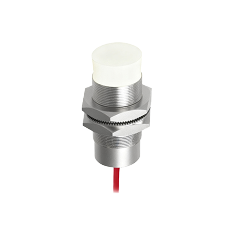
In the realm of industrial automation and control systems, proximity switch sensors stand as fundamental components for non-contact detection. Among the various wiring configurations, the three-wire proximity sensor is arguably the most prevalent and versatile design encountered by electrical engineers and technicians. This article delves into the operational principles, wiring methodologies, key specifications, and practical application considerations for three-wire proximity switches, providing a detailed technical overview for industry professionals.
At its core, a proximity switch is a sensor that detects the presence or absence of an object without physical contact. Three-wire sensors typically incorporate a solid-state switching element, such as a transistor, within the sensor housing. The "three-wire" designation refers to the standard connection scheme: one wire for the positive supply voltage (often labeled as brown or +V), one wire for the negative supply or ground (often blue or 0V), and one wire for the output signal (often black or white). This configuration separates the power supply lines from the output signal line, offering significant advantages in noise immunity and control logic flexibility compared to two-wire versions.
The internal circuitry of a three-wire sensor is powered continuously by the supply voltage, which commonly ranges from 10-30V DC, though AC and wider DC range models are available. The output transistor acts as a switch that is toggled by the sensor's detection circuit. There are two primary output types: NPN (sinking) and PNP (sourcing). This distinction is critical for proper system integration. An NPN output switches the negative (0V) line to the load; when the sensor is activated, it connects the output wire to the common negative, effectively "sinking" current. Conversely, a PNP output switches the positive supply voltage to the load; activation connects the output wire to the positive supply, "sourcing" current. The choice between NPN and PNP is often dictated by the input logic of the connected controller, such as a PLC (Programmable Logic Controller). Many regions show a preference, with PNP being common in Europe and NPN in some Asian markets, though both are globally available.
Wiring a three-wire sensor is straightforward but requires attention to detail. For a DC sensor, the brown wire connects to the positive DC supply, the blue wire to the negative/ground, and the output wire (e.g., black) to the load. The load (a PLC input, relay coil, or indicator lamp) is then connected between the output wire and the opposite supply rail. For an NPN sensor, the load is connected between the output and the positive supply. For a PNP sensor, the load is connected between the output and the negative supply. Incorrect wiring can lead to sensor damage or malfunction. Most modern sensors include protective features like short-circuit protection, reverse polarity protection, and overload protection, enhancing their robustness in harsh industrial environments.
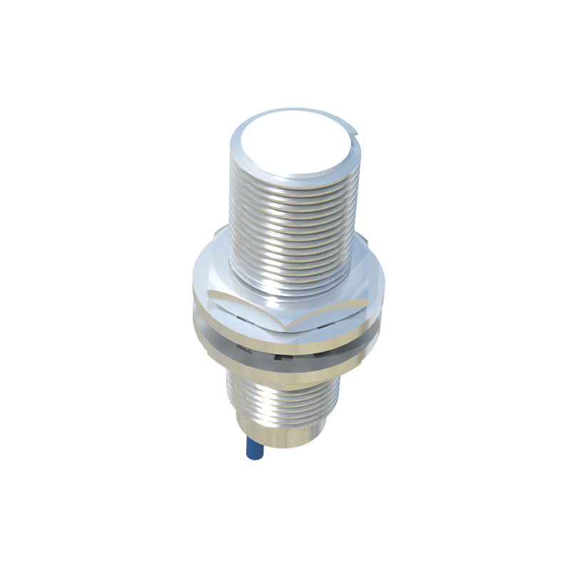
Key performance specifications for three-wire proximity switches include sensing distance, repeat accuracy, response frequency, and housing material. The nominal sensing distance, often specified for a standard mild steel target, can range from a few millimeters to several tens of millimeters. Factors like target material, size, and shape can affect the actual sensing range. Repeat accuracy refers to the sensor's ability to consistently detect an object at the same point. Response frequency, measured in Hertz, indicates how many detection cycles per second the sensor can handle, a crucial parameter for high-speed applications. Enclosures are typically made of brass, stainless steel, or PBT plastic, chosen for resistance to chemicals, temperature, and physical impact.
When selecting and applying a three-wire proximity sensor, several practical considerations are paramount. First, ensure the electrical characteristics (voltage range, output type, current rating) match the control system. Second, consider the environmental conditions: temperature extremes, presence of oils/coolants, and potential for washdowns may necessitate specific IP (Ingress Protection) ratings, such as IP67 or IP69K. Third, mounting is critical; flush-mountable sensors can be installed embedded in metal, while non-flush types require a clear area around the sensing face. Engineers must also account for mutual interference when mounting multiple sensors closely together. Finally, the choice between shielded (immune to metallic surroundings) and unshielded (offers longer sensing ranges) models depends on the installation context.
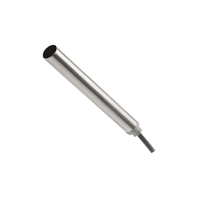
Diagnosing issues with three-wire sensors typically involves a multimeter. Checking for the correct supply voltage at the sensor terminals is the first step. Next, measure the output voltage relative to the common wire while triggering the sensor. An NPN output should switch from a high voltage (near supply voltage) to a low voltage (near 0V) when activated. A PNP output should switch from a low voltage (near 0V) to a high voltage. The status LED,