Proper installation of cylinder proximity switch sensors is critical for ensuring reliable operation in pneumatic and hydraulic systems. These sensors detect the position of a piston within a cylinder, providing essential feedback for automated control sequences. Incorrect installation can lead to false signals, mechanical damage, or complete system failure. This guide outlines the correct procedures and best practices for installing these sensors in industrial environments.
Before beginning installation, gather all necessary tools and components. You will typically need the sensor itself, mounting brackets or clamps, appropriate fasteners (such as screws or bolts), a wrench or screwdriver set, and the cylinder. Always consult the manufacturer's datasheet for specific torque values, temperature ratings, and electrical specifications. Ensure the system is depressurized and electrically isolated before starting any work to prevent injury or equipment damage.
The first step is to select the optimal mounting location on the cylinder. Most proximity sensors are designed to detect the piston's position via the cylinder's magnetic piston or a separate trigger magnet. Identify the sensing points—usually where the piston is fully retracted or fully extended. The sensor must be aligned precisely with the path of the piston or magnet. For non-magnetic cylinders, a magnetic piston ring or band may be required. Mark the mounting positions clearly using a marker.
Next, prepare the mounting surface. Clean the cylinder barrel thoroughly to remove dirt, oil, or debris that could interfere with sensor adhesion or alignment. If using a bracket or clamp, ensure it is compatible with the cylinder's diameter. Some sensors feature built-in mounting channels or adjustable slots for easy positioning. Attach the bracket to the cylinder using the provided fasteners, tightening them to the manufacturer's recommended torque. Avoid overtightening, as this may distort the sensor housing or damage the cylinder surface.
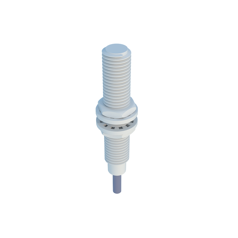
Now, install the proximity sensor into the bracket or mounting slot. Slide the sensor into position, ensuring its sensing face is perpendicular to and centered on the cylinder's axis. The gap between the sensor and the cylinder barrel should be minimal—typically 1-2 mm—but always refer to the sensor's specifications for the exact allowable distance. For inductive sensors, metallic surroundings can affect performance, so maintain clearance from other metal parts. Secure the sensor using the locking screws or fasteners, again applying the correct torque.
Wiring is the next critical phase. Most industrial proximity switches have a three-wire configuration (brown for positive, blue for negative, black for signal output) or a two-wire version. Strip the cable ends appropriately and connect them to the control system's input module according to the wiring diagram. Use conduit or cable glands for strain relief and environmental protection. Ensure connections are tight and insulated to prevent short circuits. For DC sensors, observe correct polarity; reversing power leads can damage the sensor. After wiring, perform a continuity test with a multimeter to verify electrical integrity.
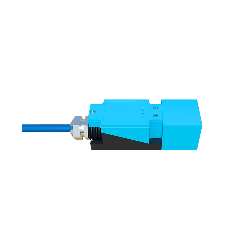
Once physically installed and wired, it's time to test the sensor. Re-energize the system cautiously. Actuate the cylinder slowly and observe the sensor's indicator LED (if equipped). The LED should illuminate when the piston or magnet passes within the sensing range. Use a programmable logic controller (PLC) or diagnostic tool to monitor the signal status. Adjust the sensor's position minutely if the detection is inconsistent or fails. Fine-tuning may involve loosening the mounting screws slightly, shifting the sensor, and retightening. Repeat the cycle until reliable triggering is achieved at both stroke ends.
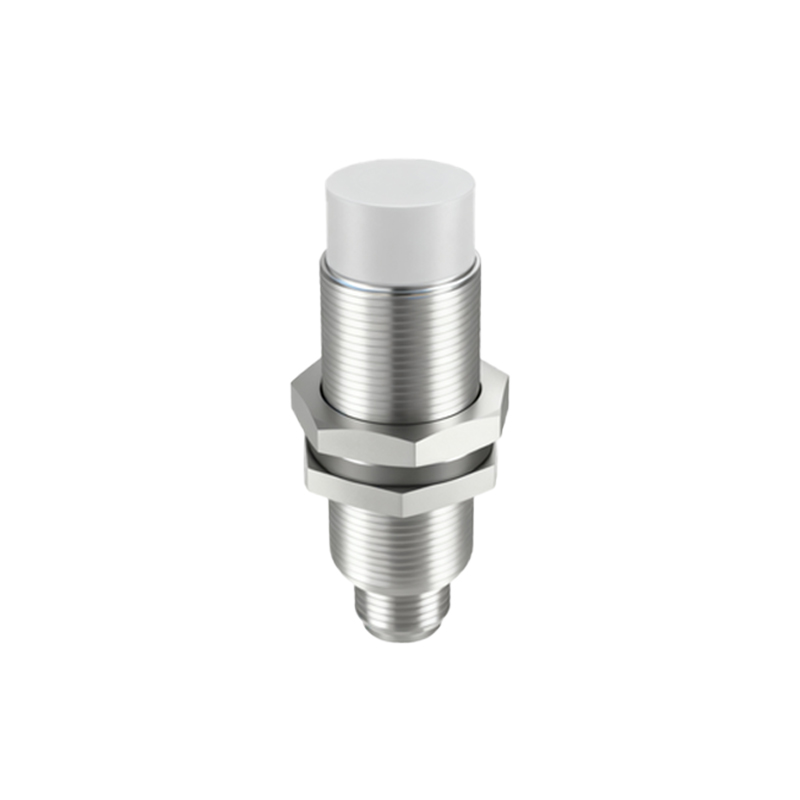
Consider environmental factors that could impact long-term performance. In high-vibration settings, use locking nuts or thread-locking compounds on fasteners. For wet or corrosive environments, select sensors with appropriate IP (Ingress Protection) ratings, such as IP67 or higher, and ensure seals are intact. Regularly inspect sensors for physical damage, loose connections, or accumulation of metallic swarf that could interfere with operation.
In summary, successful installation of cylinder proximity switches hinges on precise mechanical alignment, correct wiring, and thorough testing. Adhering to manufacturer guidelines and accounting for application-specific conditions will maximize sensor lifespan and system reliability. These components are vital for automation safety and efficiency, making proper installation not just a technical task, but a cornerstone of operational excellence.