Proximity sensors, particularly inductive types, are fundamental components in industrial automation, offering non-contact detection of metallic objects. Proper wiring of their inductive loops is critical for reliable operation, safety, and system longevity. This guide details the correct procedures and considerations for wiring proximity sensor inductive loops, adhering to industry standards and best practices.
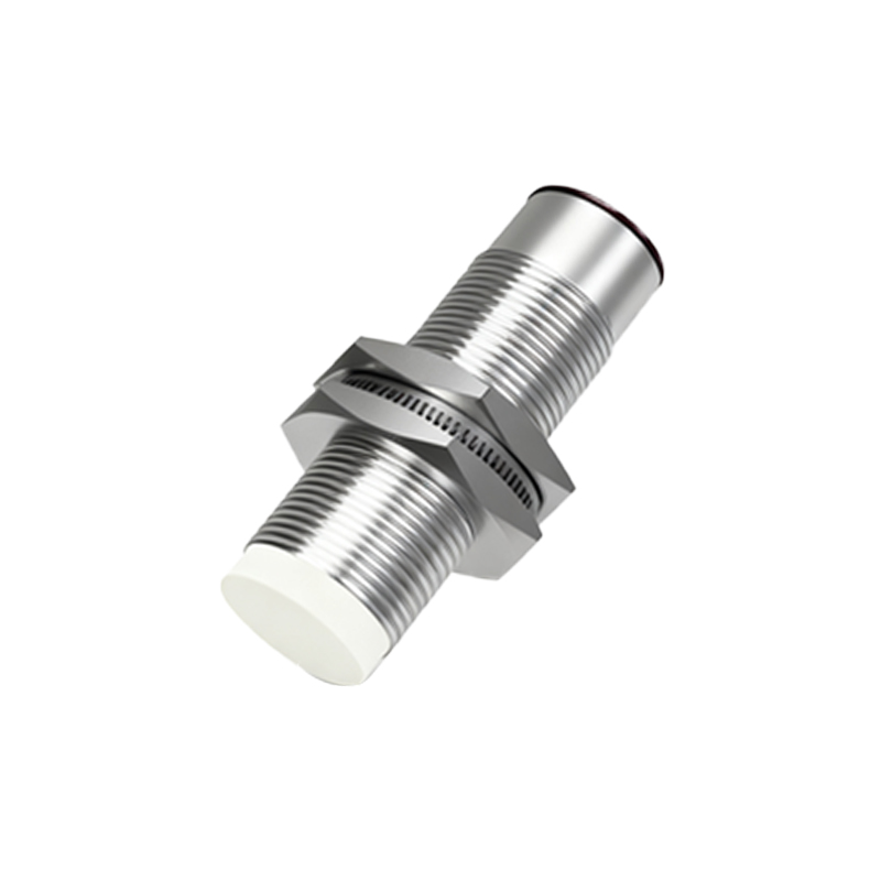
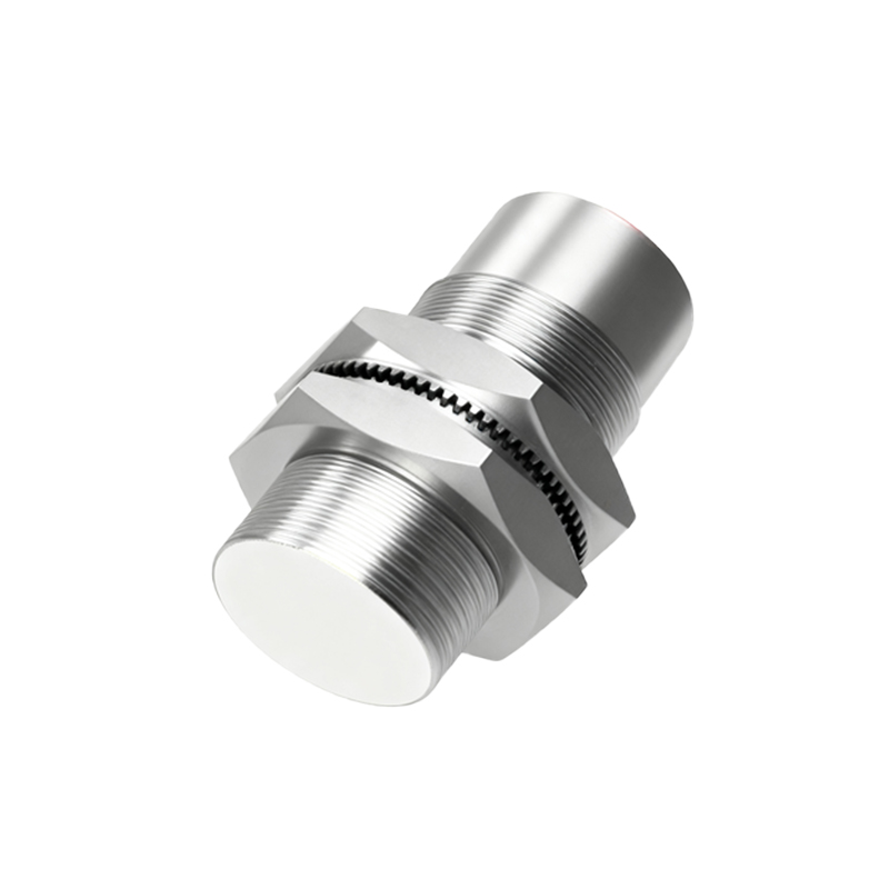
First, understand the basic components. An inductive proximity sensor typically consists of a sensing face, housing, and a cable or connector with multiple wires. Common configurations include 3-wire and 4-wire DC sensors, and 2-wire AC/DC sensors. The inductive loop refers to the internal oscillator circuit that generates an electromagnetic field. Wiring connects this sensor to a power supply and a load, such as a programmable logic controller (PLC) input or a relay.
For a standard 3-wire DC inductive proximity sensor (the most common type), the wires are usually color-coded: brown for positive voltage supply (+V), blue for negative or common (0V), and black for the output signal. The wiring process is as follows:
1. Power Supply Connection: Ensure the power supply voltage matches the sensor's rated voltage (e.g., 10-30V DC). Connect the brown wire to the positive terminal of the DC power supply. Connect the blue wire to the negative terminal. This powers the sensor's internal electronics and the inductive oscillator loop.
2. Output Signal Connection: The black wire is the switch output. For an NPN (sinking) output sensor, the black wire connects to the load (e.g., PLC input), and the other side of the load connects to the positive supply. For a PNP (sourcing) output, the black wire connects to the load, and the load's other side connects to the negative supply. The output acts as a switch that closes when a metal target enters the sensing range, completing the circuit.
3. Shield Connection (if applicable): Some sensors have an additional shield or ground wire (often yellow/green). This should be connected to a solid earth ground point at the power supply or control panel to minimize electrical noise interference, which is crucial for the stability of the inductive loop.
For 2-wire AC sensors, wiring is simpler but requires careful load matching. The two wires are connected in series with the AC power supply and the load. Polarity is not a concern for AC, but the sensor's leakage current must be considered to avoid accidental activation of the load. Always verify the sensor's maximum load current is not exceeded.
Key wiring considerations for optimal inductive loop performance:
- Cable Selection: Use shielded cables in electrically noisy environments. Keep sensor cables away from high-voltage power lines, motor drives, or welding equipment to prevent electromagnetic interference that can disrupt the inductive field.
- Wiring Practices: Employ proper strain relief at cable entries. Avoid running sensor cables in parallel with power cables; cross them at right angles if necessary. Keep wiring runs as short as possible to reduce voltage drop and noise pickup.
- Power Supply Quality: Use a stable, regulated DC power supply. Ripple or voltage fluctuations can cause erratic sensor behavior. In some cases, adding a filter or a surge protector is advisable.
- Testing and Diagnostics: After wiring, test the sensor with a target metal. Use a multimeter to check voltage at the output wire. For 3-wire sensors, the output voltage should swing close to supply voltage (for PNP) or near 0V (for NPN) when activated. LED indicators on the sensor housing provide visual confirmation of power and output status.
- Safety First: Always lock out and tag out power sources before wiring. Ensure all connections are tight and insulated. Follow local electrical codes and machinery safety standards (e.g., IEC, NEC).
Common wiring mistakes include incorrect voltage application, confusing NPN and PNP outputs, neglecting shield grounding, and overloading the output. For instance, connecting an NPN sensor output as if it were PNP will result in no signal change. Always consult the sensor's datasheet for the specific wiring diagram, as colors and functions can vary by manufacturer.
In summary, correct wiring of proximity sensor inductive loops involves matching power requirements, correctly connecting output types, implementing noise reduction strategies, and rigorous testing. Proper installation ensures the inductive loop operates with high repeatability, fast response, and minimal false triggers, thereby enhancing the reliability and efficiency of the entire automated system. Regular maintenance checks on connections and cable integrity are recommended for long-term performance.