In industrial automation and machinery control, proximity sensors are indispensable components for non-contact detection of objects. An anomaly in a proximity sensor indicates a deviation from its normal operational parameters, leading to unreliable or failed detection. Understanding what these anomalies mean is crucial for maintaining system integrity, preventing downtime, and ensuring safety. This article delves into the common causes, diagnostic procedures, and corrective actions for proximity sensor abnormalities.
What Constitutes a Proximity Sensor Anomaly?
An anomaly is any behavior where the sensor does not perform as per its specified datasheet. This can manifest in several ways:
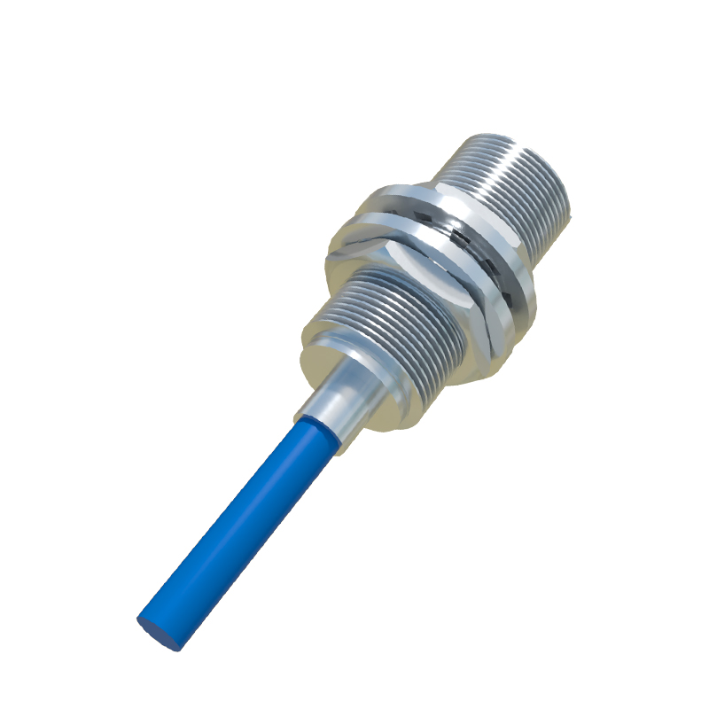
1. No Output Signal: The sensor fails to switch its output state (e.g., from OFF to ON or vice versa) when a target enters its sensing range.
2. Intermittent Operation: The output signal flickers or becomes unstable, even with a stable target present.
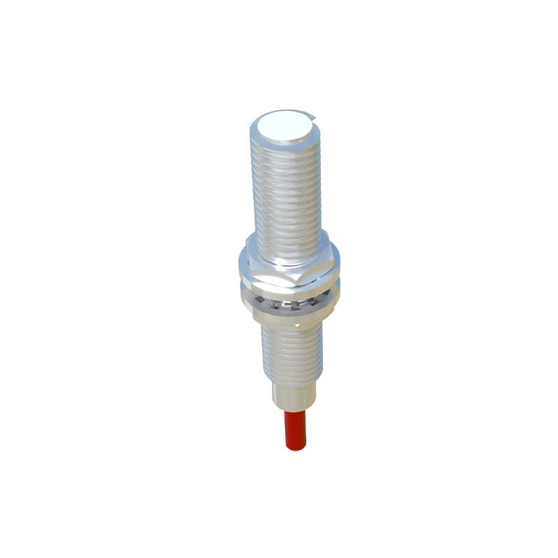
3. Reduced Sensing Distance: The sensor only detects targets at a distance significantly shorter than its rated sensing range.
4. False Triggering: The sensor activates without a valid target present, often due to environmental interference.
5. Output Stuck: The output remains permanently in either the ON or OFF state, regardless of target presence.
Primary Causes of Anomalies
Identifying the root cause is the first step in resolution. Common culprits include:
Electrical Issues: Voltage spikes, surges, or incorrect power supply (e.g., using AC on a DC sensor) can damage internal circuitry. Improper wiring, such as reversed polarity or short circuits, is a frequent installation error.
Environmental Factors: Accumulation of metallic dust, chips, or other debris on the sensor face can shield or alter its electromagnetic or capacitive field. Exposure to excessive moisture, oils, coolants, or corrosive chemicals can degrade housing seals and damage components. Extreme temperatures beyond the sensor's specification can cause drift or failure.
Mechanical Factors: Physical damage from impacts, vibration leading to loose connections, or misalignment between the sensor and its target path can cause erratic behavior.
Electrical Noise (EMI/RFI): Strong electromagnetic interference from nearby motors, variable frequency drives (VFDs), welding equipment, or high-current cables can induce false signals in the sensor or its wiring.
Sensor Degradation: Over time, internal electronic components can age or fail. For inductive sensors, the oscillator coil may weaken. For capacitive sensors, the dielectric properties may change.
Incompatible Target: Using a target that is too small, made of the wrong material (e.g., a non-ferrous metal for a standard inductive sensor), or has an unsuitable surface finish can lead to detection failures.
Systematic Diagnostic Approach
A methodical troubleshooting process is recommended:
1. Visual Inspection: Check for obvious physical damage, contamination on the sensing face, and secure cable connections.
2. Verify Specifications: Confirm the power supply (voltage, AC/DC), output type (PNP/NPN, NO/NC), and current rating match the system requirements and sensor labeling.
3. Monitor Output State: Use a multimeter or a programmable logic controller (PLC) input status indicator to observe the sensor's output behavior in real-time with and without a target. This helps identify intermittent issues or stuck outputs.
4. Check Load and Wiring: Ensure the load (e.g., PLC input, relay coil) is within the sensor's switching capacity. Inspect the wiring for continuity, proper shielding, and correct routing away from noise sources.
5. Substitution Test: If possible, replace the suspect sensor with a known-good unit of the same model. If the problem disappears, the original sensor is faulty.
Corrective Actions and Best Practices
Based on the diagnosis, apply the appropriate fix:
For Electrical Issues: Ensure a stable, clean power supply. Use surge protectors or isolation transformers if needed. Double-check and correct all wiring per the manufacturer's diagram.
For Environmental Factors: Install sensors with an appropriate Ingress Protection (IP) rating for the environment. Use protective baffles or shrouds to guard against physical impact and debris buildup. Implement regular cleaning schedules.
For Noise Interference: Use shielded cables and ground the shield properly at one end. Physically separate sensor cables from power lines. Install ferrite cores on cables near noise sources. Consider using sensors with built-in noise immunity.
General Maintenance: Adhere to a preventive maintenance schedule that includes sensor inspection, cleaning, and functional testing. Keep a stock of critical spares to minimize downtime.
In conclusion, a proximity sensor anomaly is a symptom of an underlying issue ranging from simple installation errors to complex environmental or electrical problems. By systematically diagnosing