In industrial automation systems, proximity sensors and motors often work in tandem to achieve precise control and monitoring. Properly connecting these components is crucial for ensuring operational efficiency, safety, and reliability. This guide outlines the fundamental steps and considerations for integrating proximity sensors with motors, tailored for electrical engineers and technicians in the field.
Proximity sensors are non-contact devices that detect the presence or absence of objects within a specific range. Common types include inductive, capacitive, and photoelectric sensors, each suited for different applications. Motors, such as AC induction motors or servo motors, drive mechanical systems. The connection between sensors and motors typically involves interfacing the sensor output with a motor controller or programmable logic controller (PLC) to enable automated responses, like starting, stopping, or adjusting motor speed based on sensor signals.
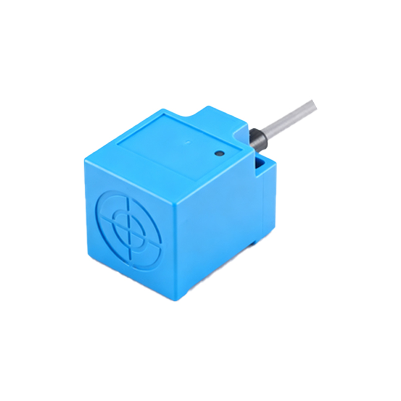
First, select the appropriate proximity sensor based on the application requirements. For metallic object detection near motors, inductive sensors are ideal due to their immunity to environmental factors like dust or oil. Ensure the sensor’s sensing range, output type (e.g., NPN or PNP), and voltage rating (commonly 12-24V DC) match the motor control system. For instance, in a conveyor system, a sensor might detect items on a belt and signal the motor to start or stop accordingly.
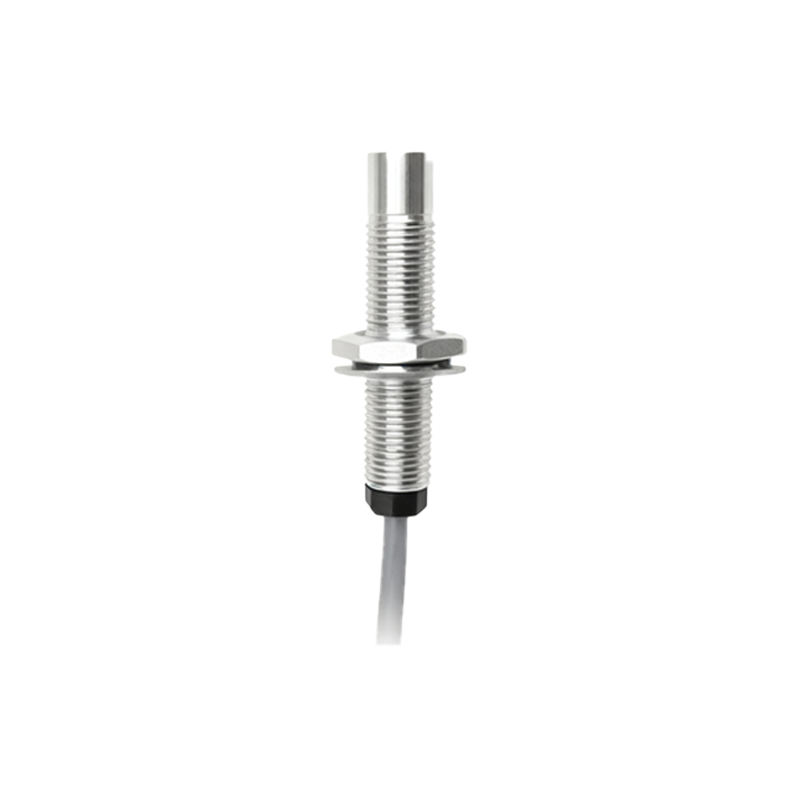
Wiring is a critical step. Begin by powering the sensor according to the manufacturer’s specifications. Connect the sensor’s power supply wires to a stable DC source, often shared with the motor controller. For the output connection, link the sensor’s signal wire to the input terminal of the motor controller or PLC. If using a relay or solid-state switch for isolation, integrate it between the sensor and controller to protect against electrical noise or voltage spikes, which are common in motor environments. Ground all components properly to minimize interference and ensure safety.
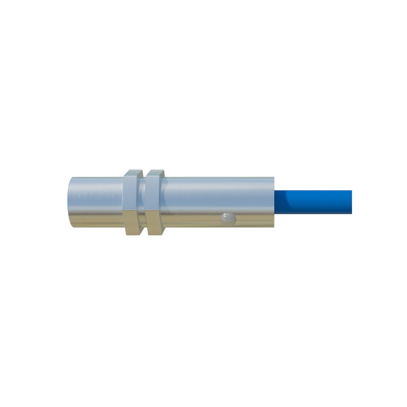
Programming the control system is next. In a PLC-based setup, write a ladder logic or structured text program to interpret the sensor’s signal. For example, when the sensor detects an object, it sends a high or low signal to the PLC, which then triggers the motor to activate via an output module. Adjust parameters like delay timers or debounce settings to prevent false triggers from motor vibrations or electromagnetic interference. For servo motors, additional feedback loops might be necessary to fine-tune position control based on sensor data.
Testing and troubleshooting are essential. After connections are made, simulate operational conditions to verify the sensor responds accurately and the motor behaves as expected. Use a multimeter to check voltage levels and continuity. Common issues include misaligned sensors, wiring errors, or incompatible signal levels. Ensure the sensor is mounted securely at an optimal distance from the target, avoiding direct exposure to heat or moving parts of the motor. Regular maintenance, such as cleaning sensor surfaces and inspecting cables, can prevent downtime.
In summary, connecting proximity sensors to motors involves careful selection, wiring, programming, and testing. By following these steps, engineers can enhance automation systems for applications like packaging, assembly lines, or robotics, improving precision and productivity. Always refer to technical datasheets and adhere to industry standards, such as IEC or NFPA guidelines, for safe and effective implementation.