Inductive proximity sensors are fundamental components in industrial automation, widely used for non-contact detection of metallic objects. As an experienced electrical engineer, I will guide you through the process of creating a basic inductive proximity sensor. This project is ideal for understanding the underlying principles and can be adapted for prototyping or educational purposes. Please note that while this guide provides a functional design, commercial sensors incorporate advanced features for reliability and safety in harsh environments.
The core operating principle is electromagnetic induction. The sensor generates an oscillating electromagnetic field via a coil. When a metallic target enters this field, eddy currents are induced in the target, which in turn dampens the oscillation amplitude of the sensor's LC tank circuit. This change is detected and converted into a switching signal.
Key Components Required:
1. Ferrite Core Coil: This is the sensing element. You can wind your own coil around a ferrite core. The inductance value is critical; a typical range is between 1 mH to 10 mH. The number of turns and core geometry will determine the sensing range, which for a homemade sensor will be relatively short (a few millimeters).
2. Oscillator Circuit: This circuit drives the coil. A simple design uses a transistor (like a BJT or MOSFET) in a Colpitts or Hartley oscillator configuration, powered by a low DC voltage (e.g., 12-24V DC).
3. Demodulation and Detection Circuit: This part rectifies and filters the AC signal from the oscillator to produce a DC voltage that changes with oscillation amplitude. A diode and a capacitor form a basic envelope detector.
4. Schmitt Trigger or Comparator: This component converts the analog DC signal from the detector into a clean, digital ON/OFF signal. An operational amplifier (Op-amp) like the LM393 configured as a comparator is a standard choice. Hysteresis is added via feedback resistors to prevent output chatter when the target is at the exact detection threshold.
5. Output Stage: For a simple PNP (sourcing) or NPN (sinking) transistor output, you will need a power transistor (e.g., a BJT or a MOSFET) to handle the load, such as a relay or PLC input. Include a flyback diode if driving an inductive load.
6. Power Supply Regulation: Ensure stable voltage for the oscillator and comparator circuits using voltage regulators or Zener diodes.
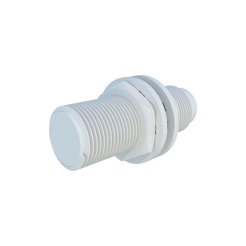
7. Housing: A cylindrical metal or robust plastic housing shields the electronics and allows for mounting.
Construction Steps:
Step 1: Coil Winding and Characterization.
Wind enameled copper wire tightly around a ferrite rod or pot core. For a preliminary design, aim for 100-200 turns. Measure the final inductance (L) using an LCR meter. This coil, in parallel with a capacitor (C), will form your LC tank circuit. The resonant frequency (f = 1/(2π√LC)) is typically in the range of 100 kHz to 1 MHz.
Step 2: Build the Oscillator.
Assemble the oscillator circuit on a breadboard or PCB. Connect the LC tank to the feedback network of the oscillator transistor. Apply power and use an oscilloscope to verify a clean, sustained sine wave oscillation at the coil. The absence of a target is your "normal" oscillating state.
Step 3: Implement the Detection Circuit.
Connect the output from the oscillator coil to the envelope detector (diode and capacitor). Probe this point with an oscilloscope; you should see a DC voltage. Now, bring a piece of mild steel close to the coil face. You should observe a measurable drop in this DC voltage as the oscillation is dampened. Adjust the capacitor values in the detector for an optimal response time without excessive ripple.
Step 4: Integrate the Comparator.
Feed the DC signal from the detector into the non-inverting input of your comparator circuit (e.g., LM393). Set a reference voltage (using a voltage divider) at the inverting input. This reference defines the detection threshold. When the sensor DC voltage drops below this reference (target present), the comparator output should switch states. Calculate and add resistor-based hysteresis to stabilize the switching.
Step 5: Add the Output Stage.
Connect the comparator's output to the base of your output transistor (e.g., an NPN transistor for a sinking output). The collector-emitter path will switch your load. Ensure current-limiting resistors are in place. For a standard 3-wire sensor configuration, you will have Brown (V+), Blue (V-), and Black (Switched Output) wires.
Step 6: Testing and Calibration.
Power the complete circuit.