Proximity sensors are indispensable components in modern industrial automation, offering non-contact detection of metallic or non-metallic objects. Among various configurations, the 3-wire proximity sensor is the most widely adopted due to its balance of functionality, reliability, and ease of integration. Understanding its correct wiring methodology is crucial for ensuring optimal performance, safety, and longevity of both the sensor and the control system. This guide delves into the principles and step-by-step procedures for wiring 3-wire proximity sensors, tailored for electrical engineers and technicians.
A standard 3-wire proximity sensor typically comprises three distinct leads: brown, blue, and black. These colors are generally consistent across manufacturers following international standards (IEC/EN 60947-5-2), though verifying the specific datasheet is always recommended. The brown wire is universally designated for the positive supply voltage (+V). The blue wire is the common negative or ground connection (0V). The black wire is the output signal line. The core function revolves around the sensor's output type, which is either NPN (sinking) or PNP (sourcing). This distinction dictates how the output signal interacts with the load (e.g., a PLC input, relay, or indicator).
For a PNP-type 3-wire sensor, the output actively sources current to the load. In this configuration, the brown wire connects to the positive terminal of the DC power supply (commonly +24V DC). The blue wire connects to the negative terminal (0V). The black output wire is connected to one terminal of the load. The other terminal of the load is then connected to the power supply's negative (0V). When the sensor detects a target, it switches the internal transistor, allowing current to flow from the brown wire (through the sensor's internal circuit) out through the black wire, through the load, and back to the blue wire/negative supply, thus activating the load. PNP sensors are often described as "positive switching."
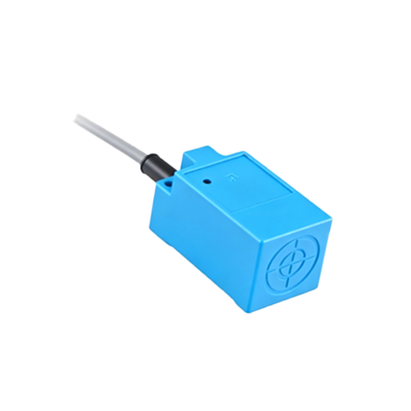
Conversely, an NPN-type 3-wire sensor operates as a sinking device. The wiring for the power supply remains identical: brown to positive (+V) and blue to negative (0V). However, the output logic is inverted. The black output wire is connected to one terminal of the load. The other terminal of the load is connected to the positive supply (+V). When activated, the sensor's internal transistor switches, providing a path for current to flow from the load, into the black wire, through the sensor, and out to the blue wire/negative supply, effectively sinking the current to ground. This completes the circuit and activates the load. NPN sensors are termed "negative switching."
The choice between PNP and NPN is primarily determined by the control system's input module requirements. Many PLCs in Europe and systems designed with "positive logic" favor PNP inputs, while NPN is common in Asia and in systems with "negative logic." Mismatching the sensor type with the PLC input can result in non-operation. A critical safety step before energizing any circuit is to meticulously check the sensor's model number and datasheet to confirm its output type, voltage range (typically 10-30V DC), and current rating.
Practical wiring procedure begins with securing and isolating the power source. Strip the insulation from the sensor's leads and the supply wires appropriately. Using ferrules or terminal blocks is highly recommended for a secure, vibration-resistant connection. First, connect the blue wire to the DC power supply's negative (0V) or common terminal. Next, connect the brown wire to the DC positive terminal (+V). Finally, route the black output wire to the designated input point on your controller (PLC, relay module, etc.). For a PNP sensor, the controller's input common should be tied to negative. For an NPN sensor, the input common should be tied to positive. Always ensure wire gauges are suitable for the current draw, and route cables away from high-voltage power lines or motor drives to prevent electrical noise interference, which can cause false triggering.
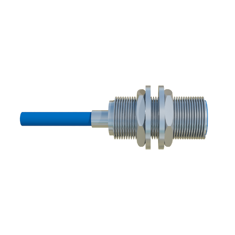
Troubleshooting common issues often involves a systematic approach. If the sensor fails to activate, verify power supply voltage at the brown and blue wires with a multimeter. Check for correct output type (PNP/NPN) compatibility. Inspect the black wire's connection to the load and ensure the load itself is functional. A sensor that is permanently "on" might indicate wiring errors, such as a short circuit, or that the sensing face is contaminated or too close to a metallic background. Always adhere to lock-out/tag-out (LOTO) procedures during installation and maintenance.
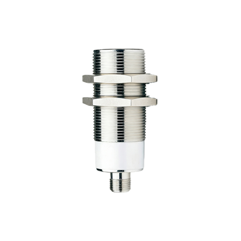
In summary, mastering the 3-wire proximity sensor connection is a fundamental skill. By correctly identifying the PNP or NPN output, meticulously following the color-coded wiring