In industrial automation and electrical control systems, proximity switches are indispensable components for detecting the presence or absence of objects without physical contact. Proper wiring is crucial for ensuring reliable operation, safety, and longevity of these sensors. One common area of confusion, especially for those new to electrical installations, involves connecting the live and neutral wires correctly. This article provides a clear, professional guide on wiring proximity switches, focusing on AC-powered models, which typically require live and neutral connections.
First, it is essential to understand the basic types of proximity switches. They are broadly categorized into AC (alternating current) and DC (direct current) versions. AC-powered proximity switches, often operating at voltages like 120VAC or 240VAC, require both a live (hot) wire and a neutral wire to function. In contrast, DC models usually have two or three wires (positive, negative, and sometimes a signal output) and do not involve a neutral in the traditional sense. This guide concentrates on AC types, as they directly relate to live and neutral wiring.
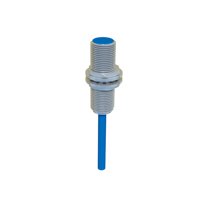
Before starting any wiring work, always adhere to safety protocols. Disconnect power from the circuit, verify it is de-energized using a multimeter or voltage tester, and follow local electrical codes and standards. Wear appropriate personal protective equipment (PPE). Incorrect wiring can lead to sensor failure, equipment damage, or even electrical hazards such as short circuits or shocks.
A typical AC proximity switch has three or four terminals, commonly labeled as L (Live), N (Neutral), and LOAD (or sometimes OUT). Some models may include an additional ground terminal for safety. The live wire (often brown or black, depending on regional color codes) carries the incoming AC voltage. The neutral wire (usually blue or white) completes the circuit, providing a return path for the current. The load wire connects to the device being controlled, such as a relay, PLC input, or indicator lamp.
Step-by-step wiring procedure:
1. Identify the terminals: Check the sensor’s datasheet or housing label for terminal designations (L, N, LOAD). Do not rely solely on wire colors, as they can vary.
2. Connect the live wire: Strip the insulation from the live wire and securely attach it to the L terminal. Ensure the connection is tight to prevent arcing or overheating.
3. Connect the neutral wire: Similarly, connect the neutral wire to the N terminal. This provides the necessary return path. In some configurations, the neutral may also be shared with the load; always follow the manufacturer’s diagram.
4. Connect the load: Attach the load wire to the LOAD terminal. This wire will carry the switched output to your control device.
5. Ground connection: If a ground terminal (marked PE or with a ground symbol) is present, connect the protective earth wire (green/yellow) to it. This enhances safety by preventing electric shock in case of insulation failure.
A critical point to remember is that the load should be connected in series with the switch output. For example, in a normally open (NO) configuration, when the sensor detects an object, it closes the internal switch, allowing current to flow from L through the sensor to the LOAD, and then to the neutral or back to the power source, depending on the circuit design. Miswiring, such as swapping live and neutral, can cause the sensor to malfunction or become permanently energized, leading to premature failure.
Additionally, consider the electrical load specifications. Proximity switches have maximum current and voltage ratings for the output. Exceeding these ratings can damage the sensor. Always verify that the connected load (e.g., a relay coil) is within the sensor’s capacity. For inductive loads like solenoids or contactors, using surge suppression devices (such as RC networks or varistors) is recommended to protect the sensor from voltage spikes.
In three-wire AC proximity switches, the wiring is similar, but the neutral might be internally linked. Again, consult the specific wiring diagram. Some advanced sensors feature built-in diagnostics or LED indicators that help troubleshoot wiring errors—for instance, a steady LED might indicate correct power connection, while a blinking pattern could signal a fault.
Finally, after wiring, perform a thorough check. Inspect all connections for tightness and proper insulation. Restore power and test the sensor by introducing a target object within its sensing range. Use a multimeter to verify the output voltage at the LOAD terminal when activated. Ensure there is no abnormal heating or humming from the sensor, which could indicate loose connections or overload.
In summary, correct wiring of proximity switches involves careful identification of live and neutral terminals, secure connections, and adherence to safety standards. By following these guidelines, engineers and technicians can ensure