In the realm of industrial automation and control systems, magnetic proximity switch sensors stand as a cornerstone for reliable position detection, object counting, and speed monitoring. Among the various configurations available, the 3-wire magnetic proximity sensor is particularly prevalent due to its balanced combination of performance, simplicity, and integration ease. This article delves into the operational principles, wiring configurations, key specifications, and practical application considerations for these essential components.
At its core, a magnetic proximity switch sensor operates on the principle of detecting the presence or absence of a magnetic field, typically from a permanent magnet. Unlike inductive or capacitive sensors that detect metallic or material presence, magnetic sensors respond specifically to magnetic flux. The fundamental sensing element is often a reed switch or a Hall-effect integrated circuit. A reed switch consists of two ferromagnetic, hermetically sealed reeds within a glass envelope. When an external magnetic field of sufficient strength is applied, the reeds attract each other, making contact and closing the circuit. Hall-effect sensors, on the other hand, generate a voltage output proportional to the magnetic field strength when a current flows through a semiconductor material in the presence of a magnetic field. This voltage signal is then conditioned by internal electronics to produce a clean switching output.
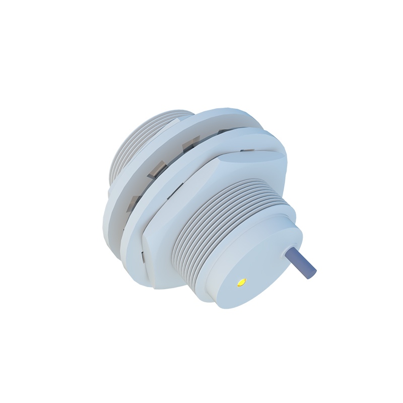
The defining feature of a 3-wire sensor is its power and output configuration. It requires three distinct connections:
1. Brown Wire (or L+): This is the positive supply voltage line. Common operating voltages for DC sensors include 10-30 VDC, though specific ranges vary by model.
2. Blue Wire (or L- / M): This is the negative supply voltage line or the common/ground return.
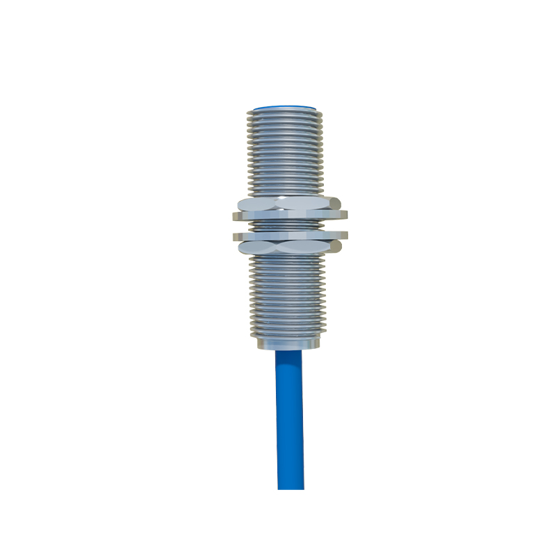
3. Black Wire (or OUT): This is the switched output signal line. The nature of this output is critical and is defined as either NPN (sinking) or PNP (sourcing).
Understanding NPN and PNP outputs is paramount for correct integration. An NPN output sensor internally connects the black output wire to the negative (blue) line when the sensor is activated (magnet detected). This means it sinks current to ground. To complete the circuit, the load (e.g., a PLC input, relay coil) must be connected between the positive supply (brown) and the black output wire. Conversely, a PNP output sensor internally connects the black output wire to the positive (brown) supply when activated. It sources current. Here, the load must be connected between the black output wire and the negative (blue) line. Selecting the wrong type for your control system (typically PLCs are specified for either sinking or sourcing inputs) will result in a non-functional circuit.
Key technical specifications guide the selection process for 3-wire magnetic proximity sensors:
Sensing Distance: The nominal operating distance (Sn) at which a standard magnet will reliably trigger the switch. This is typically short-range, from a few millimeters up to about 40-50 mm for powerful sensors.
Switching Frequency: The maximum number of on/off cycles per second the sensor can handle, crucial for high-speed counting applications.
Output Type: As discussed, NPN normally-open (NO), NPN normally-closed (NC), PNP NO, or PNP NC.
Hysteresis: The difference between the switch-on point (magnet approaching) and switch-off point (magnet retreating). This feature prevents chatter or rapid switching when the magnet is at the exact threshold distance.
Protection Rating (IP Code): Indicates resistance to dust and water ingress (e.g., IP67 is common, allowing temporary immersion).
Temperature Range: Specifies the operational ambient temperature limits.
The advantages of 3-wire DC magnetic sensors are significant. They provide a solid-state, non-contact switching solution, leading to exceptionally long mechanical life as there are no moving parts subject to wear (especially in Hall-effect types). They are immune to contaminants like dust, oil, and non-ferrous chips, making them ideal for harsh industrial environments—machine tools, material handling, automotive assembly, and door/window position sensing in hazardous areas. Their response is fast and independent of the target's approach speed. Compared to 2-wire AC/DC sensors, 3-wire versions offer lower voltage drop and leakage current, allowing them to interface more reliably with modern programmable logic controllers (PLCs) and low-power electronic controls.
For successful implementation, several application tips must be considered. First, always ensure correct polarity when connecting the brown (+) and blue (-) wires to the DC power supply; reverse polarity can permanently damage the sensor's internal electronics. Second, verify the compatibility of the output type (NPN/PN