Proximity sensors, particularly the widely adopted P20 series, are fundamental components in modern industrial automation and control systems. As an inductive sensor, the P20 is designed for non-contact detection of metallic objects, offering reliability, durability, and precision in harsh environments. Understanding its correct application is crucial for system integrity and performance. This guide details the practical steps and considerations for using a P20 proximity sensor effectively.
First and foremost, selecting the correct P20 model is paramount. The P20 series typically includes variants with different sensing ranges (e.g., 2mm, 5mm, 8mm), output types (NPN normally open/closed, PNP normally open/closed), and connection methods (pre-wired cable or quick-disconnect). Engineers must match the sensor to the target material (ferrous metals like iron and steel provide the standard sensing distance; non-ferrous metals like aluminum or copper require a reduced effective range), the required output logic for the PLC or controller, and the available power supply (commonly 10-30V DC). Always consult the specific datasheet for the exact model number before installation.
Installation and mounting require careful attention. Ensure the sensor is securely fastened in its designated location using the appropriate hardware. A critical rule is to maintain the specified nominal sensing distance (Sn) between the sensor's active face and the target object. For side-by-side mounting of multiple sensors, maintain a minimum distance between them—usually one to two times the sensor diameter—to prevent mutual interference. Also, avoid mounting the sensor directly facing or in extreme proximity to other large metal structures besides the target, as this can cause false triggering. The sensing field is frontal; metallic objects approaching from the side are generally not detected.
Wiring the P20 sensor correctly is a straightforward but vital process. For a standard 3-wire DC sensor:
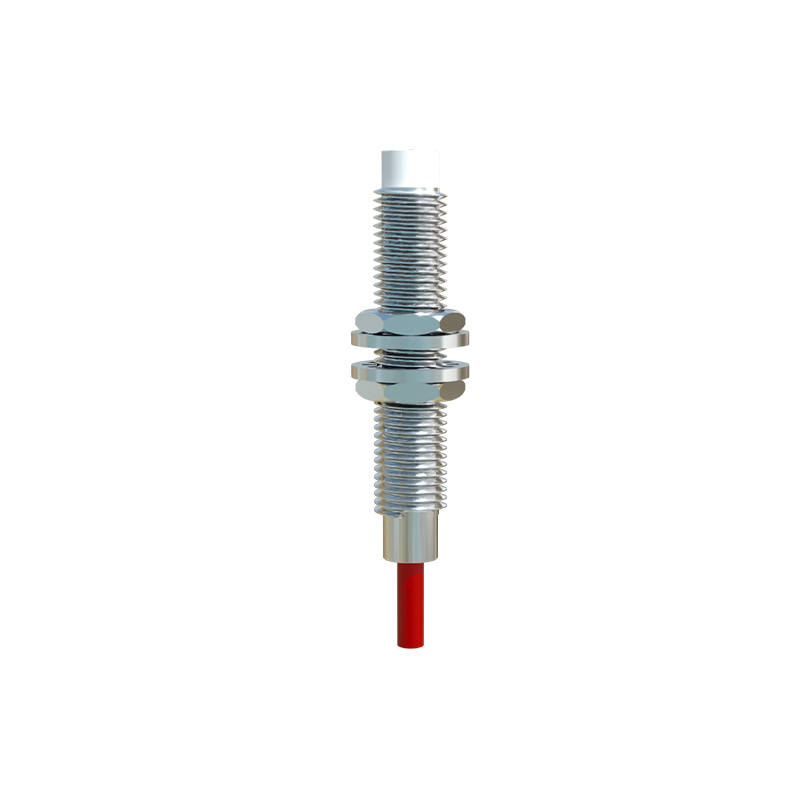
1. Identify the wires: Typically, brown wire is for positive DC supply (+V), blue wire is for negative/ground (0V), and black wire is the switched output signal.
2. For an NPN output sensor (sinking output), the black wire connects to the PLC input, and the PLC input's common is connected to positive voltage. When activated, the NPN sensor sinks current to ground, completing the circuit to the PLC input.
3. For a PNP output sensor (sourcing output), the black wire connects to the PLC input, and the PLC input's common is connected to ground. When activated, the PNP sensor sources current from the positive supply to the PLC input.
4. Always connect the blue wire to the power supply ground and the brown wire to the positive voltage within the specified range (e.g., 12-24V DC). Incorrect polarity can damage the sensor.
5. Some models may include a fourth wire for a separate output function or diagnostic LED. Refer to the wiring diagram.
Once powered, testing and adjustment are necessary. Most P20 sensors feature a built-in LED indicator that lights up when the target is within range. Use the actual target material to verify the real-world sensing distance, which may be less than the nominal Sn for non-standard metals. Check for consistent triggering and ensure there is no "chatter" or unstable signal as the target approaches and retreats. The sensor's hysteresis—the difference between the switch-on and switch-off points—prevents oscillation and is a fixed characteristic.
Integration with control systems involves connecting the sensor's output to a digital input module on a PLC, relay, or other controller. Program the logic accordingly. For instance, a normally open (NO) sensor output closes the circuit when a target is detected, sending a "high" or "1" signal to the input. Consider adding a small debounce delay in the PLC logic if needed to filter out electrical noise, though P20 sensors are generally resistant to common industrial interference.
Maintenance and troubleshooting are minimal but important. Periodically clean the sensor face from accumulated dirt, metal shavings, or oil, as these can marginally reduce the effective sensing range. If a sensor fails, check the power supply voltage first, then verify wiring connections. Use a multimeter to measure the output voltage state with and without a target present. Remember, these sensors have a finite operational life, though it is typically very long (millions of cycles).
In summary, the effective use of a P20 proximity sensor hinges on correct model selection, precise mechanical installation, accurate electrical wiring, and thorough testing. By adhering to these principles, electrical engineers can ensure robust object detection, contributing to the seamless and reliable operation of automated machinery, conveyor systems, robotic cells, and safety interlocks. The P20's simplicity and robustness make it an enduring solution for countless industrial sensing applications.