Proximity sensor testers are indispensable diagnostic tools in modern industrial automation and electrical maintenance. Their primary function is to verify the operational status, sensing range, output signal, and overall health of inductive, capacitive, and sometimes magnetic proximity sensors without requiring the sensor to be removed from its installed location or connected to the actual control system. Correct usage is critical for efficient troubleshooting, preventive maintenance, and ensuring system uptime. This guide details the standard operational procedure for using a universal proximity sensor tester.
1. Pre-Use Safety and Preparation
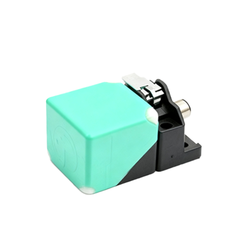
Before beginning any testing, adhere to all site-specific Lockout/Tagout (LOTO) procedures and safety protocols. Ensure the sensor's power supply is disconnected if the tester requires direct connection to the sensor's terminals. For non-contact testers that simulate a target, ensure the machinery is in a safe, non-operational state. Visually inspect the sensor for physical damage, corrosion, or loose wiring. Identify the sensor type (e.g., inductive, capacitive, DC/AC, NPN/PNP) and its nominal operating voltage, typically listed on the sensor body. Select a tester compatible with these specifications.
2. Understanding Tester Types and Connections
There are two main categories of testers: Simulative Testers and Direct-Connection Testers.
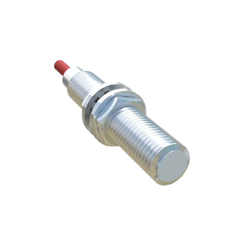
Simulative Testers: These devices generate an electromagnetic field or provide a physical metal target. They are used to check if a powered sensor activates when a target enters its sensing range. No electrical connection to the sensor is made.
Direct-Connection Testers: These units connect directly to the sensor's output wires or quick-disconnect plug. They typically supply the necessary operating voltage to the sensor and provide a visual indication (LED, buzzer) of the sensor's switching state. Some advanced models can also measure leakage current, output voltage, switching frequency, and response time.
3. Step-by-Step Testing Procedure with a Direct-Connection Tester
This is the most common method for bench testing or installed sensor verification.
Step A: Power Off & Connect. De-energize the sensor circuit. Connect the tester's leads to the sensor's wires: the red lead to the positive (+) wire (typically brown), the black lead to the negative (-) wire (typically blue), and the output monitoring lead (often yellow or green) to the sensor's signal wire (typically black or white). For 2-wire AC sensors, connect the tester in series with the sensor and load.
Step B: Configure Tester. Set the tester's voltage switch to match the sensor's rating (e.g., 10-30V DC for most). Select the correct output type (NPN sinking or PNP sourcing).
Step C: Apply Power & Test Sensing. Turn on the tester. The tester now supplies power to the sensor. An LED on the tester should indicate the sensor's current state (usually OFF). Introduce a valid target (e.g., a piece of mild steel for inductive sensors) to the sensor's active face. The tester's indicator should change state (e.g., LED lights, buzzer sounds), confirming the sensor switches correctly.
Step D: Check Sensing Distance. Gradually move the target toward the sensor face. Note the distance at which the tester indicates activation. Compare this to the sensor's rated nominal sensing distance (Sn). Activation significantly outside the specified range (e.g.,< 80% of Sn) may indicate a failing or contaminated sensor.
Step E: Evaluate Output Signal. Advanced testers can quantify the output. For a DC sensor, a healthy "ON" state voltage should be close to 0V for NPN or close to the supply voltage for PNP. A high residual voltage in the ON state (excessive leakage) can cause PLC input errors.
4. Using a Simulative (Non-Contact) Tester
For quick in-situ checks, a simulative tester is ideal. Power the sensor through its normal circuit. Hold the tester's active end near the sensor's sensing face. Activate the tester (often via a button). A good sensor will react as if a metal target is present, and its built-in LED will illuminate, and its output will switch. This confirms basic functionality without disconnection.
5. Interpreting Results and Troubleshooting
No Response to Target: Check connections, power supply polarity, and tester configuration. The sensor may be defective or the wrong type (e.g., trying to sense a non-metallic object with an inductive sensor).
Inconsistent or Reduced Sensing Distance: Often caused by sensor face contamination (oil, metal chips), misalignment, or a weakened internal oscillator circuit. Clean the face thoroughly.