In the rapidly evolving landscape of electric vehicles (EVs) and smart charging infrastructure, the charging port proximity sensor has become a critical safety and communication component. This sensor, typically a Hall-effect or inductive type, detects the presence and correct insertion of the charging connector, enabling the vehicle's management system to initiate and monitor the charging process safely. Improper wiring can lead to communication failures, safety hazards, or damage to the onboard charger and battery system. This guide provides a detailed, industry-standard procedure for correctly wiring a charging port proximity sensor.
First and foremost, safety is paramount. Before beginning any electrical work, ensure the vehicle's high-voltage system is fully isolated and disabled according to the manufacturer's lock-out/tag-out (LOTO) procedures. Verify zero voltage at the charging port terminals using a certified CAT III or IV multimeter. Personal protective equipment (PPE), including insulated gloves and safety glasses, is mandatory.
Step 1: Identify the Sensor Type and Pinout
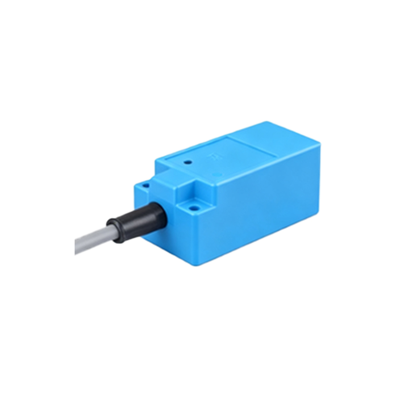
Locate the sensor, usually integrated into the charging inlet housing. Consult the vehicle's service manual or the sensor's datasheet. Common configurations include 3-pin (Supply, Ground, Signal) or 4-pin (adding a diagnostic line) connectors. Identify:
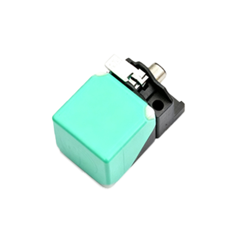
Vcc: Supply voltage (commonly +5V or +12V DC, vehicle-specific).
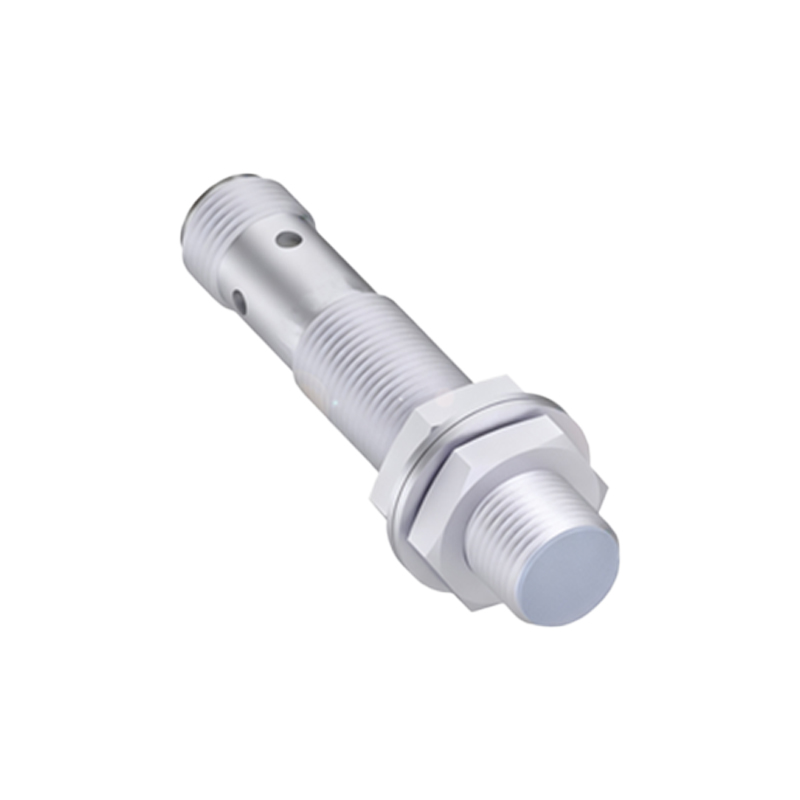
GND: Ground reference.
SIG / OUT: Digital or PWM signal output.
DIAG (if present): Diagnostic feedback line.
Step 2: Prepare the Wiring Harness
Use automotive-grade, cross-linked polyethylene (XLPE) or similar insulated wires with a gauge appropriate for the current (usually 20-22 AWG is sufficient for signal lines). Ensure the harness includes necessary fuses, connectors, and shielding if specified. Route the harness away from high-voltage cables, moving parts, and heat sources. Use conduit or loom for mechanical protection.
Step 3: Connect Power and Ground
1. Identify a stable, fused power source matching the sensor's Vcc requirement from the vehicle's low-voltage distribution center. Do not tap into random circuits.
2. Connect the sensor's Vcc wire to this source via the appropriate connector. Install an in-line fuse (typically 2A to 5A) as close to the power tap as possible.
3. Connect the sensor's GND wire to a dedicated, clean chassis ground point. Scrape away paint or corrosion to ensure a metal-to-metal contact. Use a star washer and proper torque.
Step 4: Connect the Signal Output
This is the most critical connection. The SIG wire must be routed to the designated input pin on the vehicle's charge port control module (CPCM) or the main vehicle control unit (VCU).
1. Locate the correct pin on the controller connector using the wiring diagram.
2. Crimp or solder the terminal pin to the SIG wire using proper tools. A poor connection here will cause intermittent faults.
3. Insert the terminal into the controller connector housing until it clicks securely into place.
Step 5: Shielding and Noise Mitigation
If the sensor datasheet specifies a shielded cable, ensure the shield is properly grounded at one end only (typically the controller end) to prevent ground loops. Avoid running signal lines parallel to high-current AC cables from the charger; cross them at a 90-degree angle if necessary.
Step 6: Initial Verification and Testing
Before restoring system power:
Perform a continuity test to check for short circuits between Vcc and GND, and between SIG and GND/Vcc.
Verify insulation resistance between the sensor wiring and the high-voltage terminals.
Visually inspect all connections for correctness and security.
Step 7: Power-On Functional Test
1. Restore low-voltage power.
2. Using a digital oscilloscope or a high-impedance multimeter, probe the SIG line at the controller connector.
3. Test 1 (No Connector): The signal should read a defined "idle" state (e.g., 0V, 5V, or a specific PWM duty cycle).
4. Test 2 (Connector Inserted): Insert the charging connector. The signal should change to the defined "active" state (e.g., voltage toggle or PWM change). This change confirms the sensor is detecting the connector and the wiring is communicating correctly to the controller.
5. If a DIAG line is present, check its specified voltage or resistance values.
Step 8: System Integration Test
Initiate a full charging cycle. Monitor the vehicle's diagnostic system for any proximity sensor-related fault codes (e