In the realm of industrial automation and control systems, proximity sensors are indispensable components for non-contact object detection. A rapid proximity sensor, specifically designed for high-speed applications, relies on a well-engineered schematic diagram that dictates its performance, reliability, and integration capabilities. This article delves into the fundamental principles and typical schematic representation of such a sensor, focusing on inductive-type sensors commonly used for metallic target detection.
The core operational principle of an inductive proximity sensor is based on electromagnetic induction. The schematic diagram fundamentally illustrates an oscillator circuit, a detection circuit, a signal amplifier, and an output stage. At the heart of the oscillator is a coil (L) wound around a ferrite core, which, together with a capacitor (C), forms a resonant LC tank circuit. This circuit generates a high-frequency electromagnetic field at the sensing face. When a metallic object enters this oscillating field, eddy currents are induced on the surface of the target. These eddy currents draw energy from the oscillator, causing a reduction in the oscillation amplitude.
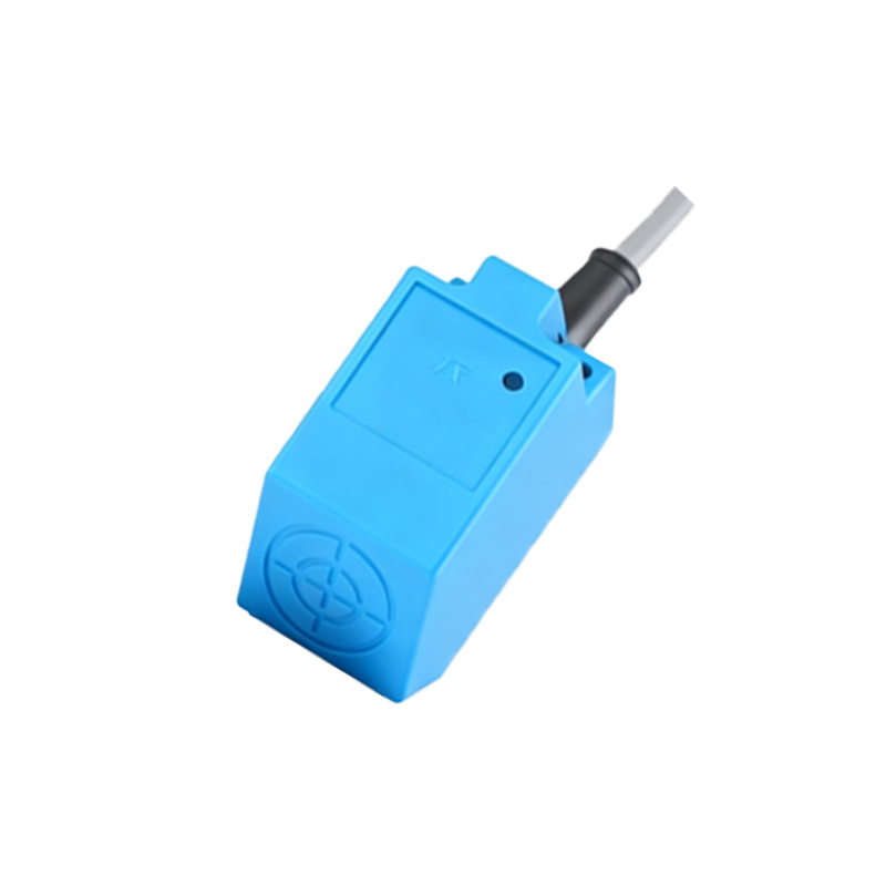
The schematic clearly shows how this amplitude change is monitored. The detection circuit, often a demodulator or a peak detector, converts the AC oscillation signal into a DC voltage level proportional to the amplitude. This DC signal is then fed into a comparator or a specialized integrated circuit (IC). The comparator compares this signal against a predefined reference voltage (Vref), which is set to correspond to the detection threshold. In a rapid proximity sensor, the design of this comparator stage is critical for minimizing response time. High-speed operational amplifiers or dedicated sensor ICs with fast switching characteristics are employed.
Once the sensed signal crosses the threshold, the comparator's output state changes. This triggers the output stage. The schematic typically depicts this as a solid-state switch, most commonly an NPN or PNP transistor, or a MOSFET for very high-speed switching. For a 3-wire DC sensor, the output transistor is in series with the load (e.g., a PLC input, relay, or indicator). The diagram shows the connection of the collector (for NPN) or emitter (for PNP) to the load, with the other terminal connected to the positive supply (for NPN sourcing) or negative/ground (for PNP sinking). Protection components are vital and are clearly indicated: a free-wheeling diode across the load for inductive loads to suppress voltage spikes, and often a series resistor or a TVS (Transient Voltage Suppressor) diode to protect the output transistor from overvoltage.
Power supply conditioning is another key area visible in the schematic. A voltage regulator (like a 78xx series or a low-dropout regulator) ensures a stable internal voltage (e.g., 5V or 3.3V) for the oscillator and ICs, independent of fluctuations in the external supply voltage (commonly 10-30V DC). Decoupling capacitors are placed near the ICs to filter high-frequency noise, which is crucial for stable operation in electrically noisy industrial environments and for preventing false triggering—a must for rapid and reliable detection.
For sensors with diagnostic or programmability features, the schematic may include a microcontroller unit (MCU). The MCU monitors the detection signal, can implement adjustable sensing ranges or delays, and may drive an LED status indicator. Communication lines for IO-Link or other industrial protocols would also be shown branching from the MCU.
Analyzing the schematic of a rapid proximity sensor reveals design priorities: a stable, high-frequency oscillator for sensitivity; a fast-response, low-hysteresis comparator circuit; a robust and swift output switching stage; and comprehensive protection and filtering against electrical interference. Understanding this schematic is essential for engineers not only for troubleshooting but also for selecting the right sensor for high-speed counting, precise positioning, or safety interlocking applications where every millisecond of response time counts. The elegance of the design lies in its ability to convert a subtle change in an electromagnetic field into a crisp, rapid, and reliable digital signal that drives modern automated processes.