In industrial automation and control systems, the integration of proximity sensors with relays is a fundamental and powerful technique. This combination forms the backbone of countless applications, from simple presence detection to initiating complex sequential operations. A proximity sensor, acting as the "eyes" of the system, detects the presence or absence of a target object without physical contact. The relay, serving as the robust "muscle," uses this signal to control a higher-power circuit, such as a motor, solenoid valve, or warning lamp. This article provides a detailed, step-by-step guide on correctly wiring a standard 3-wire DC proximity sensor to a relay, ensuring reliable and safe operation.
Understanding the Core Components
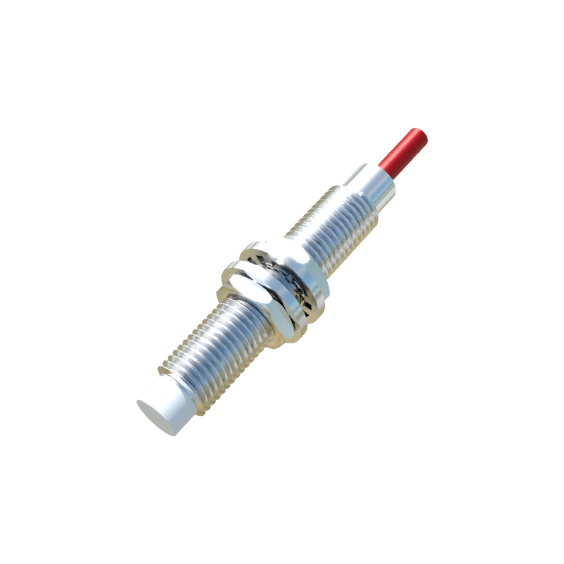
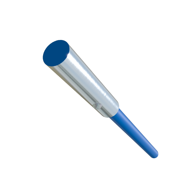
First, let's clarify the key players. A typical 3-wire DC proximity sensor has three distinct wires: Brown (or Red), Blue, and Black (or White, Yellow, depending on the output type). The Brown wire is connected to the positive DC supply voltage (e.g., +24VDC). The Blue wire is connected to the DC common or 0V. The Black wire is the signal output wire. For a Normally Open (NO) sensor, this output wire switches to supply voltage (+24VDC) when a target is detected. For a Normally Closed (NC) sensor, the output is at supply voltage when no target is present and switches to 0V when detected.
The relay is an electromechanical switch. It has a coil and a set of contact terminals. When a sufficient voltage is applied across the coil terminals (A1 and A2), it creates a magnetic field that pulls the internal contacts, changing their state (e.g., from open to closed). The coil typically operates at a low DC voltage like 24VDC. The contacts are rated for higher currents and voltages (e.g., 10A at 240VAC) and are electrically isolated from the coil circuit.
System Design and Wiring Procedure
The primary goal is to use the sensor's output to energize the relay's coil. Here is a systematic wiring procedure:
1. Power Supply Setup: Establish a stable DC power source, commonly 24VDC. The negative terminal (0V or DC-) will be our common reference point for the circuit.
2. Sensor Power Connection:
Connect the Brown wire of the proximity sensor to the positive terminal (+24VDC) of the power supply.
Connect the Blue wire of the sensor to the negative terminal (0V) of the power supply. The sensor is now powered and its indicator LED should be on (possibly blinking, depending on the model and target presence).
3. Relay Coil Connection (The Critical Link):
Identify the relay coil terminals, usually labeled A1 (positive) and A2 (negative).
Connect one side of the relay coil (terminal A2) directly to the 0V (negative) of the power supply.
Now, connect the other side of the relay coil (terminal A1) to the Black (output) wire of the proximity sensor. This is the core of the interface. When the sensor detects a target, its output wire becomes "live" (+24VDC). This voltage is now applied directly to the relay coil terminal A1. Since A2 is connected to 0V, a complete circuit is formed, current flows through the coil, and the relay energizes.
4. Load Circuit Wiring:
The relay's switched contacts (e.g., terminals 13 (common) and 14 (normally open)) are now used to control your main load (e.g., a motor starter, lamp, or another device).
Connect the hot wire of your load's power source (e.g., 120VAC Line) to the common terminal (13) of the relay contact.
Connect the normally open terminal (14) of the relay contact to one side of the load device.
Complete the load circuit by connecting the other side of the load device back to the neutral of the load's power source.
Practical Considerations and Best Practices
Sensor Type (NPN vs. PNP): The wiring described above is for a PNP type sensor (also known as "sourcing" output). Its output provides positive voltage. An NPN (sinking) sensor's output switches to 0V when activated. To use an NPN sensor with a standard relay coil, you would connect A1 to +24VDC and connect A2 to the sensor's output (Black wire). The relay energizes when the sensor output sinks to 0V.
Flyback Di