Radar proximity sensors are essential components in modern industrial automation, offering non-contact detection capabilities for various applications. Understanding the wiring diagram is crucial for proper installation, ensuring optimal performance and safety. This guide provides a detailed overview of radar proximity sensor wiring, including key components, step-by-step connection instructions, and common troubleshooting tips.
Radar proximity sensors operate by emitting high-frequency radio waves and analyzing the reflected signals to detect objects within a specified range. These sensors are widely used in manufacturing, automotive, and security systems due to their reliability and accuracy. The wiring diagram typically includes power supply connections, output signals, and grounding points. Most radar sensors require a DC power supply, commonly 12V or 24V, which must be connected according to the manufacturer's specifications to prevent damage.
The wiring process begins with identifying the sensor's terminals, usually labeled on the housing or in the datasheet. Key terminals include V+ (positive power), V- (negative power or ground), and output signals such as NO (normally open) or NC (normally closed) for relay-type sensors, or analog outputs like 4-20mA for continuous detection. For digital sensors, additional terminals may be provided for communication protocols like IO-Link or Modbus. It is essential to use shielded cables to minimize electromagnetic interference, especially in environments with high electrical noise.
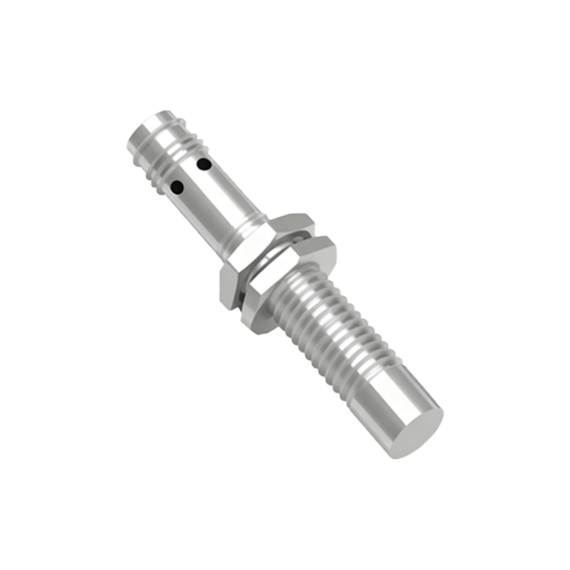
When connecting the sensor, first ensure the power is off to avoid short circuits. Connect the V+ terminal to the positive wire of the power supply and the V- terminal to the negative wire. For output connections, link the sensor's output terminal to the control device, such as a PLC (Programmable Logic Controller) or relay module. If the sensor includes a diagnostic LED, verify its operation during power-up to confirm proper wiring. Grounding is critical for safety and performance; connect the sensor's ground terminal to a reliable earth ground using a low-resistance path.
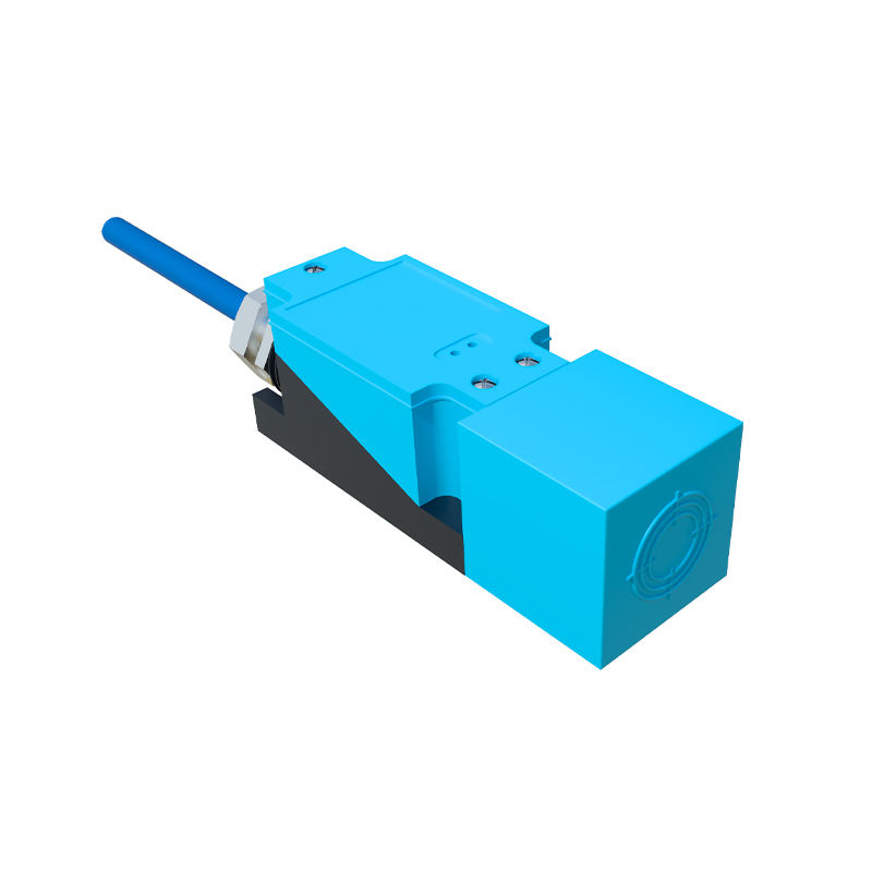
In complex systems, multiple sensors may be wired in parallel or series, depending on the application requirements. Always refer to the specific wiring diagram provided by the sensor manufacturer, as configurations can vary based on model and functionality. For example, some radar sensors feature adjustable sensing ranges or sensitivity settings, which may require additional wiring for configuration inputs.
Common wiring issues include incorrect polarity, loose connections, or inadequate cable sizing, leading to sensor malfunction or false triggers. To troubleshoot, check all connections with a multimeter for continuity and voltage levels. Ensure the power supply matches the sensor's rated voltage and that the load connected to the output does not exceed its capacity. Regular maintenance, such as inspecting cables for wear and cleaning sensor lenses, can prevent long-term problems.
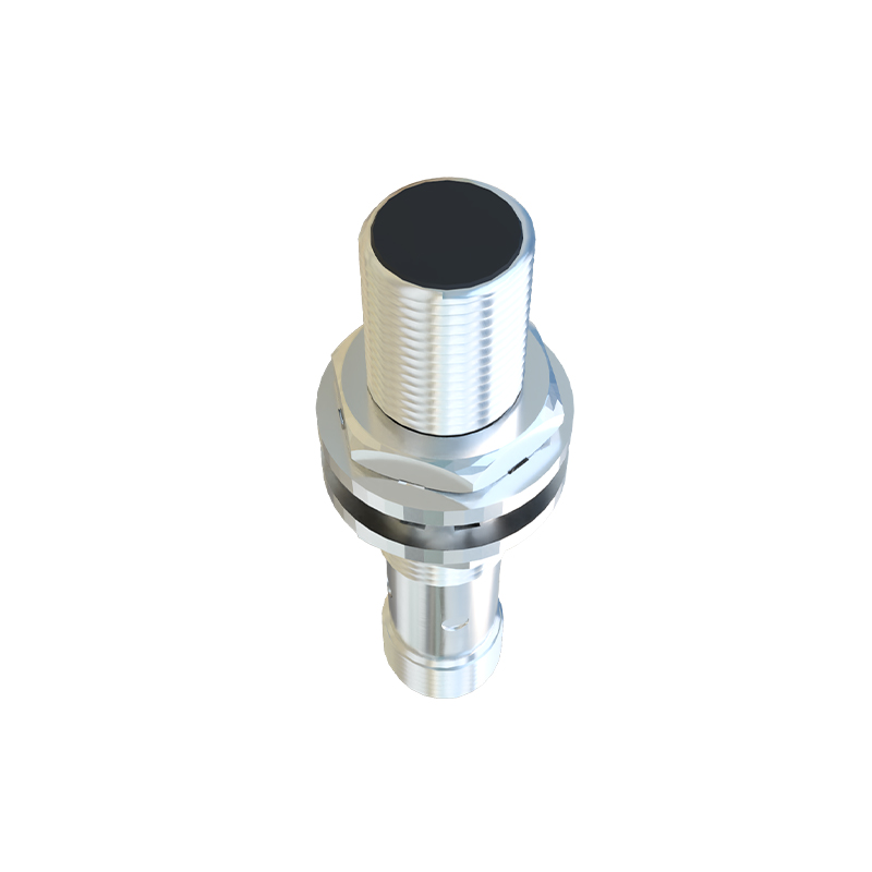
In summary, proper wiring of radar proximity sensors is fundamental to their effectiveness in industrial settings. By following the wiring diagram meticulously and adhering to safety standards, engineers can achieve reliable object detection and enhance system automation. For advanced applications, consulting technical documentation or seeking professional assistance is recommended to address specific challenges.