Flat proximity switch sensors, also known as flat inductive proximity sensors, are critical components in industrial automation, packaging machinery, and material handling systems. Their low-profile design allows for installation in tight spaces where standard cylindrical sensors cannot fit. Determining whether a flat proximity sensor is functioning correctly is essential for maintaining system uptime and preventing costly failures. This guide outlines a systematic, industry-standard approach to testing these sensors.
1. Preliminary Visual and Physical Inspection
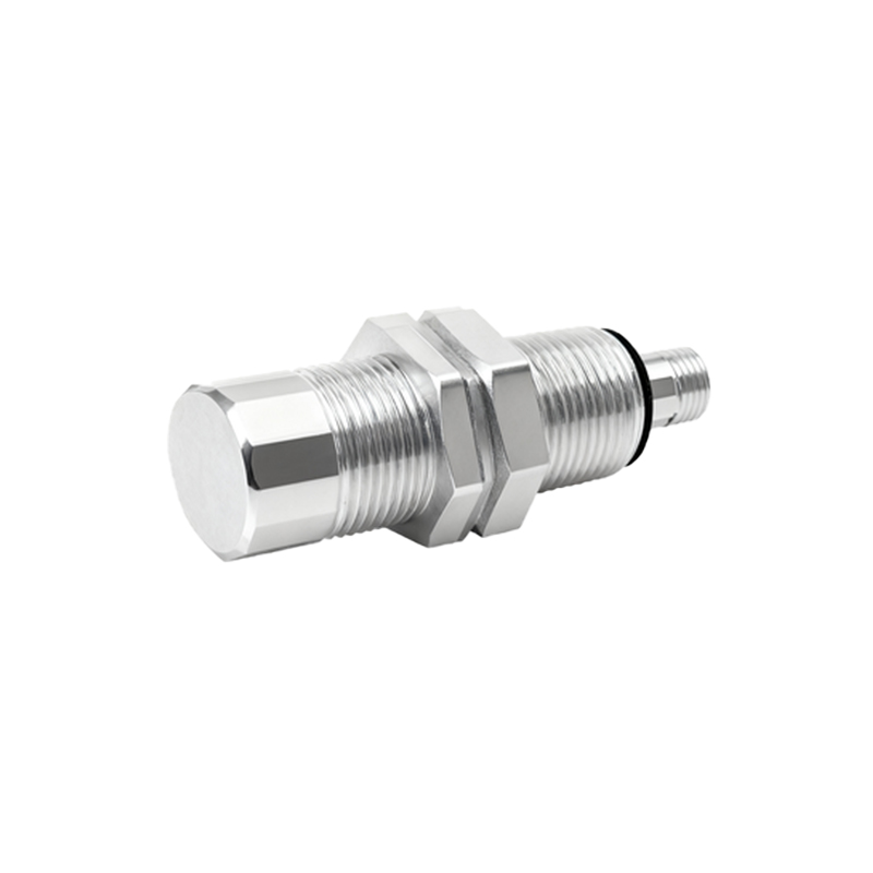
Before any electrical testing, conduct a thorough visual inspection. Check the sensor's housing for any cracks, dents, or signs of impact damage. Examine the sensing face for accumulated dirt, metal shavings, grease, or other contaminants that could attenuate the sensing field. Clean the face gently with a soft, lint-free cloth and an appropriate solvent if necessary. Verify that the mounting is secure and that there is no undue mechanical stress on the sensor body or cable. Inspect the cable for cuts, abrasions, or damage to the insulation, especially at the entry point to the sensor and the connector.
2. Review of Specifications and Setup
Locate the sensor's datasheet or model number. Critical parameters to note include:
Sensing Distance (Sn): The nominal operating distance. Testing beyond this range may yield false negatives.
Operating Voltage: Typically 10-30V DC for 3-wire models. Ensure your power supply matches.
Output Type: NPN (sinking) or PNP (sourcing), normally open (NO) or normally closed (NC). This dictates the testing procedure.
Output Current: Do not exceed the maximum current rating.
Installation Conditions: Some flat sensors require a minimum distance from metal mounting surfaces (flush-mountable vs. non-flush-mountable). Incorrect mounting can reduce the effective sensing distance.
3. Electrical Testing Procedure
Safety First: Disconnect power to the machine or circuit before making any connections. Use appropriate personal protective equipment (PPE).
For 3-Wire DC Sensors (Most Common):
1. Basic Wiring: Connect the sensor per its wiring diagram. Generally:
Brown wire (+V): Connect to the positive terminal of your DC power supply (e.g., 24V).
Blue wire (0V): Connect to the negative terminal/common.
Black wire (Output): Connect to your test load (e.g., a multimeter, a pilot lamp, or the input of a PLC). For an NPN sensor, the load is connected between the output and +V. For a PNP sensor, the load is connected between the output and 0V.
2. Power On: Apply the correct operating voltage.
3. State Check without Target:
For a Normally Open (NO) sensor, the output should be OFF (no voltage for PNP, full voltage for NPN when measured relative to common). The status indicator LED (if present) should be off.
For a Normally Closed (NC) sensor, the output should be ON. The LED should be on.
4. Actuation Test with Target: Introduce the correct target material (usually mild steel) to the sensing face. Move it slowly and axially towards the face.
For an NO sensor, the output should switch ON when the target is within the specified sensing distance. The LED should illuminate. The switch point should be repeatable.
For an NC sensor, the output should switch OFF when the target is within range. The LED should turn off.
5. Measurement: Use a digital multimeter to verify switching behavior.
For a PNP NO sensor: Measure voltage between the Black (output) and Blue (0V) wires. It should read near 0V without a target and near supply voltage (e.g., 24V) with a target present.
For an NPN NO sensor: Measure voltage between the Black (output) and Brown (+V) wires. It should read near supply voltage without a target and near 0V with a target present.
Reverse the logic for NC types.
6. Hysteresis Check: Note the distance at which the sensor activates as the target approaches. Slowly move the target away and note the distance where it deactivates. The difference (hysteresis) is normal but should be within the manufacturer's specification. A lack of hysteresis or erratic switching indicates a problem.
For 2-Wire DC/AC Sensors:
Testing is similar but involves connecting the sensor in series with the load and power supply. Use a