In the realm of industrial automation, metal proximity sensors are indispensable components, providing non-contact detection of metallic objects. Their reliability and durability stem from a precise manufacturing process. This guide details the step-by-step production of a standard inductive metal proximity sensor, offering insights into the engineering principles and assembly techniques involved.
The journey begins with the core component: the sensing coil. High-grade copper wire is meticulously wound around a ferrite core within a bobbin. The number of turns and the wire gauge are calculated with extreme precision based on the target sensing range and the sensor's operating frequency, typically within the range of 100 kHz to 1 MHz. This coil, once wound, is the heart of the oscillator circuit. It is then potted or encapsulated in a thermosetting epoxy resin. This critical step serves multiple purposes: it physically secures the delicate windings against vibration and shock, provides excellent electrical insulation, and protects the coil from environmental contaminants like moisture, dust, and oils. The potting compound is cured in a controlled oven to achieve optimal mechanical and dielectric properties.
Simultaneously, the electronic circuitry is prepared. The core circuit is an LC oscillator, where the 'L' is our potted coil. Surface-mount technology (SMT) is predominantly used for its reliability and compactness. Components like the oscillator IC, resistors, capacitors, and the output driver (whether NPN, PNP, or analog) are automatically placed onto a printed circuit board (PCB) using high-precision pick-and-place machines. The PCB itself is designed with careful attention to signal integrity and noise immunity. After component placement, the board passes through a reflow soldering oven, where a carefully profiled temperature cycle creates permanent solder joints. The populated PCB then undergoes automated optical inspection (AOI) to detect any soldering defects or misplaced components.
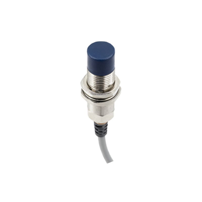
The next phase involves integrating the coil assembly with the PCB. The leads from the potted coil are soldered to designated pads on the board. For sensors with extended sensing ranges or specific form factors, a ferrite focusing cup or shield may be assembled around the coil at this stage to direct and concentrate the electromagnetic field. The entire electronic assembly is then fitted into the sensor housing.
The housing, typically machined from stainless steel (e.g., 303 or 316 grade) or nickel-plated brass, serves as the sensor's rugged exterior. The choice of material depends on the application environment; stainless steel offers superior corrosion resistance for harsh conditions. The housing is precisely machined to include threads (e.g., M8, M12, M18, M30) for mounting, and a front sensing face made of a specific material, often a wear-resistant polymer like PBT or PEEK, which allows the electromagnetic field to pass through while protecting the coil. The electronic assembly is inserted into the housing, and the sensing face is securely sealed, often using laser welding, ultrasonic welding, or a high-grade epoxy to achieve an IP67, IP68, or IP69K rating for ingress protection.
Following mechanical assembly, the sensor enters the calibration and testing phase. This is a critical quality gate. Each sensor is connected to a test jig. Key parameters are verified: the switching distance (Sn) is measured against standardized test targets (e.g., a 1mm thick square of mild steel). The hysteresis, which is the difference between the switch-on and switch-off points, is confirmed to be within specification to ensure stable switching without chatter. The electrical characteristics are tested under load—checking the output voltage drop, leakage current, and short-circuit protection. Environmental stress tests, such as temperature cycling and vibration tests, are performed on sample batches from the production line to validate long-term reliability.
Finally, the sensors are labeled with their technical specifications (sensing range, output type, voltage range, etc.) and serial numbers for traceability. They are packaged in anti-static materials to prevent damage to the sensitive electronics from electrostatic discharge (ESD) during handling and shipping.
The manufacturing of a metal proximity sensor is a synergy of electromagnetic theory, precision mechanical engineering, and robust electronic assembly. From the precise winding of the coil to the hermetic sealing of the housing, each step is governed by stringent standards to ensure the sensor performs flawlessly in demanding industrial environments, providing millions of reliable detection cycles.