In the realm of industrial automation, proximity sensors are indispensable for detecting the presence or absence of objects without physical contact. Among the various types, the 2-wire DC proximity sensor stands out for its simplicity and cost-effectiveness. Unlike its 3-wire or 4-wire counterparts, a 2-wire sensor integrates directly into the load circuit, functioning similarly to a conventional switch. However, its correct wiring is paramount for reliable operation and system longevity. This guide delves into the practical aspects of connecting a 2-wire DC proximity sensor.
Understanding the 2-Wire DC Sensor Principle
A 2-wire sensor has only two connection leads: one for the positive supply voltage (typically labeled brown or +) and one for the output signal and negative return (typically labeled blue or -). It operates in series with the load (e.g., a PLC input, relay coil, or indicator lamp). When no target is detected, a small leakage current (often less than 2 mA) flows through the sensor. Upon detecting a target within its sensing range, the internal electronic switch closes, allowing the full load current to pass through, thus activating the connected device. This "normally open" (NO) configuration is most common, though "normally closed" (NC) types are available.
Standard Wiring Procedure
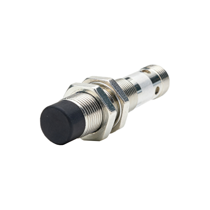
The wiring process is straightforward but requires attention to polarity and electrical ratings.
1. Power Supply Compatibility: First, verify the sensor's voltage rating (e.g., 10-30V DC). Ensure your DC power supply matches this range. An unstable or incorrect supply voltage is a leading cause of sensor malfunction.
2. Identify the Wires: The brown wire connects to the positive terminal of the DC power supply. The blue wire connects to one terminal of your load (the device you wish to control).
3. Complete the Circuit: The other terminal of the load must then be connected to the negative terminal of the DC power supply. This forms a complete series circuit: Power Supply (+) -> Brown Wire -> Sensor -> Blue Wire -> Load -> Power Supply (-).
4. Consider the Load: The sensor has a maximum switching current and a minimum required load current. Exceeding the maximum can damage the sensor. More critically, if the connected load (like a high-impedance PLC input) draws less than the sensor's minimum load current, the sensor may not switch off properly, leading to a "stuck on" state. Always consult the sensor's datasheet for these critical values.
Critical Considerations for Reliable Operation
Leakage Current: The inherent leakage current in the "off" state means a small voltage drop will always be present across the sensor. When connected to a PLC digital input, this residual voltage must be below the PLC's "OFF" voltage threshold. If it is too high, the PLC may falsely register an "ON" signal. Using a bleeder resistor in parallel with the load can often solve this issue by providing a path for the leakage current.
Short-Circuit and Overload Protection: It is highly recommended to protect the sensor circuit with a fast-acting fuse or a circuit breaker rated slightly above the sensor's operating current.
Wiring Practices: Use shielded cables in electrically noisy environments, connecting the shield to ground at only one end (usually the control panel end). Keep sensor cables away from high-voltage power lines and motor drives to prevent electromagnetic interference.
Sensor Mounting: Ensure proper mechanical mounting with adequate clearance from metal surfaces as specified by the manufacturer to avoid a reduction in the effective sensing distance.
Advantages and Limitations
The primary advantage of the 2-wire sensor is its reduced wiring complexity and lower installation cost, as it requires fewer wires and terminals. It is also easier to replace, mimicking a simple switch.
The key limitations revolve around the leakage current and load dependency. They are generally less flexible than 3-wire sensors, which have a separate supply and output, allowing for a wider range of load types without the minimum current concern. Furthermore, the voltage drop across a 2-wire sensor under load means the load receives a slightly lower voltage than the supply.
Troubleshooting Common Issues
Sensor Does Not Activate Load: Check power supply polarity and voltage. Verify the load is functional and its current draw is within the sensor's specified range. Ensure the target is within the sensor's sensing range and is of the correct material (e.g., inductive sensors detect metals).
Load Stays On: This is frequently caused by insufficient load current. Measure the current. If it is below the sensor's minimum requirement, add a dummy load (like a resistor) in parallel with the primary load to increase the total current