In industrial automation and control systems, proximity sensors are indispensable components for non-contact detection of metallic or, in some cases, non-metallic objects. Among the various types, the 3-wire DC proximity sensor is one of the most common and reliable configurations. Proper wiring is critical for ensuring sensor functionality, system safety, and longevity. This guide provides a detailed, step-by-step explanation of how to correctly wire a 3-wire DC proximity sensor, covering fundamental principles, wiring diagrams, and essential troubleshooting tips.
First, it is crucial to understand the basic operating principle and terminal identification of a standard 3-wire DC sensor. These sensors typically have three distinct wires, each color-coded for identification according to international standards, though colors can vary by manufacturer. The most common color scheme is: Brown wire for the positive supply voltage (+V or V+), Blue wire for the negative supply or common (0V or COM), and Black wire for the output signal (OUT or LOAD). The sensor operates by generating an electromagnetic field. When a target object enters this field, it causes a change in the sensor's internal oscillation, which in turn triggers the solid-state switching element (usually a transistor) to change the state of the output signal.
There are two primary output types for 3-wire DC proximity sensors: NPN (sinking) and PNP (sourcing). This distinction is fundamental and dictates how the sensor is integrated into the control circuit. An NPN output sensor switches the negative (0V) line to the load. In this configuration, the load (e.g., a PLC input, relay coil, or indicator lamp) is connected between the sensor's black output wire and the positive supply voltage (+V). When the sensor is activated, it connects the load to 0V, completing the circuit and allowing current to flow into the sensor's output terminal—hence the term "sinking." Conversely, a PNP output sensor switches the positive (+V) line to the load. Here, the load is connected between the sensor's black output wire and the negative supply (0V). Upon activation, the sensor provides the positive voltage to the load, with current flowing out from the sensor's output terminal—hence "sourcing."
The wiring procedure is systematic. Begin by ensuring the power is completely disconnected and locked out (LOTO procedure) for safety. Identify the sensor's specifications on its nameplate, noting the required supply voltage (commonly 10-30V DC) and the output type (NPN or PNP). Connect the brown wire to the positive terminal of your DC power supply. Connect the blue wire to the negative terminal or common of the same DC power supply. The connection of the black output wire depends on your output type and the device you are controlling. For an NPN sensor controlling a PLC digital input: Connect the black wire to the PLC input terminal. The same PLC input terminal will typically require an internal or external connection to +V (often through a "sourcing" input circuit or a pull-up resistor) to complete the path. For a PNP sensor controlling a PLC digital input: Connect the black wire to the PLC input terminal. The common of the PLC input module must be connected to 0V. For driving a relay coil or lamp: Connect one side of the load to the black wire. For an NPN sensor, connect the other side of the load to +V. For a PNP sensor, connect the other side of the load to 0V. Always use the correct wire gauge, ensure tight connections, and protect the wiring in conduits or cable carriers if in a harsh environment.
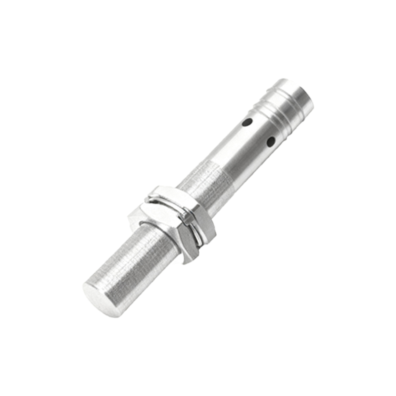
Common pitfalls include mixing up NPN and PNP wiring, which will prevent the sensor from operating. Connecting the load incorrectly, such as short-circuiting the output, can permanently damage the sensor's internal transistor. Exceeding the voltage or current ratings is another common cause of failure. Always verify the sensor's state with a multimeter. With power applied and no target present, measure the voltage between the black and blue wires. For a normally-open (NO) NPN sensor, you should read near the supply voltage. For a NO PNP sensor, you should read near 0V. When a target is presented, the voltage should switch. If the sensor fails to operate, double-check all connections, power supply integrity, and ensure the target material and sensing distance are within the sensor's specified parameters. Proper shielding and grounding are also essential in electrically noisy environments to prevent false triggering.
In summary, correctly wiring a 3-wire proximity sensor hinges on accurately identifying the output type (NPN vs. PNP) and meticulously following the corresponding circuit diagram. Adherence to safety protocols, manufacturer specifications, and standard color codes will ensure