Laser sensors are widely used in industrial automation for precise detection, measurement, and positioning tasks. Proper wiring is crucial to ensure accurate operation, safety, and longevity of the sensor. This guide provides a step-by-step approach to wiring laser sensors, covering key considerations and best practices.
First, identify the sensor type and its specifications. Laser sensors typically fall into two categories: through-beam (opposed) and reflective (diffuse or retro-reflective). Each type may have different wiring requirements based on its output configuration (e.g., NPN, PNP, analog, or digital). Refer to the sensor's datasheet for details on voltage ratings, current limits, and pin assignments. Common connections include power supply (V+ and V-), output signals, and sometimes auxiliary functions like teach-in or diagnostics.

Begin by preparing the tools and materials: a suitable power source (usually 12-24V DC for industrial sensors), appropriate cables (shielded cables are recommended to reduce electromagnetic interference), wire strippers, and connectors. Ensure the power is turned off before starting any wiring work to prevent electrical hazards or damage to the sensor.

For basic wiring, connect the power supply wires. Attach the positive wire (often brown or red) to the V+ terminal and the negative wire (blue or black) to the V- terminal. Double-check the voltage polarity; reverse polarity can permanently damage the sensor. If the sensor has a ground terminal, connect it to earth ground for enhanced noise immunity and safety.
Next, handle the output wiring based on the sensor's function. For digital output sensors (e.g., NPN or PNP types), connect the output wire to the control device, such as a PLC (Programmable Logic Controller) or relay. NPN sensors sink current to the negative side, while PNP sensors source current from the positive side—ensure compatibility with your control system. For analog output sensors (e.g., 0-10V or 4-20mA), wire the output to an analog input module, paying attention to signal integrity by avoiding long cable runs near high-voltage lines.
Some laser sensors feature additional connections for synchronization, daisy-chaining, or communication protocols like IO-Link. Follow the manufacturer's instructions for these specialized functions. After wiring, secure all connections with proper terminals or crimps to prevent loose contacts, which can cause intermittent failures.
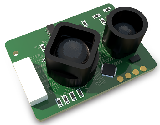
Finally, test the setup. Power on the sensor and verify its indicator lights (if available). Use a target to check detection and output response. Adjust settings like sensitivity or threshold as needed. Regularly inspect wiring for wear or corrosion, especially in harsh environments.
In summary, correct laser sensor wiring involves understanding the sensor type, using appropriate tools, following polarity guidelines, and testing thoroughly. Proper installation minimizes downtime and ensures reliable performance in automation systems.