In industrial automation and control systems, proximity sensors are indispensable components for non-contact detection of metallic or non-metallic objects. Among the various configurations, the two-wire proximity sensor is widely favored for its simplicity and ease of integration into existing control circuits. This article provides a detailed, professional guide to the two-wire wiring diagram, its operating principles, and key considerations for reliable installation and operation.
Understanding the Two-Wire Proximity Sensor
A two-wire proximity sensor, as the name implies, requires only two wires for connection: one for power supply and one for the load. This design contrasts with three-wire or four-wire sensors that have separate wires for power, ground, and signal output. The two-wire sensor operates in series with the load it controls, such as a programmable logic controller (PLC) input, a relay coil, or an indicator lamp. Its fundamental principle is based on modulating the current flow through the sensor based on the target's presence or absence. When no target is detected, a small leakage or "off-state" current flows, insufficient to activate the load. When a target enters the sensing range, the sensor's internal switching element (typically a solid-state device) turns on, allowing sufficient current to flow to energize the load.
Standard Two-Wire Wiring Diagram and Components
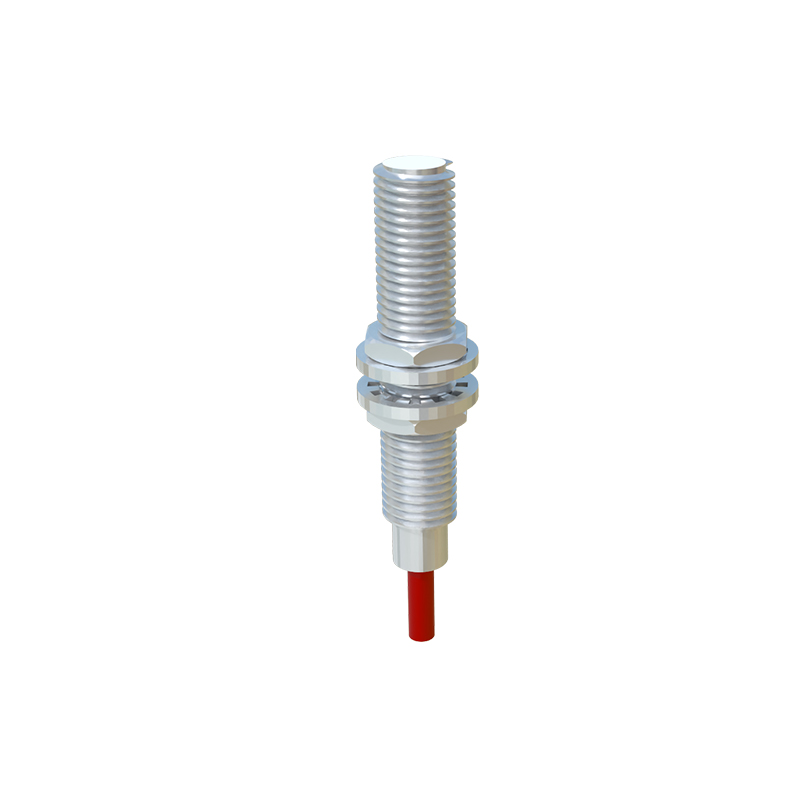
The wiring diagram for a DC two-wire proximity sensor is straightforward. The two terminals are usually labeled, with common markings being +V / L+ and Load / -V / L-. It is crucial to consult the specific sensor's datasheet for exact terminal designations. The standard connection is as follows:
1. Power Supply Connection: Connect the positive terminal (+V) of the DC power supply (commonly 10-30V DC) to one sensor terminal.
2. Load Connection: Connect the other sensor terminal to one side of the load (e.g., the PLC digital input module terminal).
3. Completing the Circuit: Connect the other side of the load back to the negative terminal of the DC power supply, forming a complete series loop: Power (+) -> Sensor -> Load -> Power (-).
For AC two-wire sensors, the wiring follows a similar series principle but with alternating current. One terminal connects to the live (L) or neutral (N) AC line, and the other terminal connects to the load, which then returns to the opposite AC line. AC sensors often incorporate circuits to manage inrush current and provide a stable switching state.
Critical Electrical Parameters and Selection
Correct application hinges on understanding key parameters:
Supply Voltage: Ensure the sensor's rated voltage (e.g., 10-30V DC, 20-250V AC) matches your control circuit voltage.
Off-State Current (Leakage Current): This is the small current (typically<1.8mA for DC) that flows when the sensor is off. It must be lower than the minimum holding current of the load to prevent false activation. For instance, some PLC inputs have a low "ON" current threshold; a high leakage current might inadvertently trigger the input.
On-State Voltage Drop: When switched on, the sensor has an internal voltage drop (usually 1.5-3V). This drop reduces the voltage available to the load. The formula is: V_load = V_supply - V_drop(sensor). You must verify that the remaining voltage is within the load's operational range.
Maximum Load Current: The sensor has a maximum current it can switch. The load's current draw must not exceed this rating. Exceeding it can permanently damage the sensor's internal switch.
Short-Circuit and Overload Protection: Many modern sensors include built-in protection, but external fusing is often recommended as a best practice.
Advantages, Limitations, and Troubleshooting Tips
Advantages: Simplified wiring reduces installation time and cost. They are ideal for replacing mechanical limit switches directly. The two-wire design is inherently safe against incorrect polarity for AC types and often for DC types as well.
Limitations: The leakage current and voltage drop can be problematic for sensitive loads. They generally have lower switching speeds compared to three-wire PNP/NPN types. The load current flows through the sensor continuously, leading to slightly higher power dissipation.
Common Troubleshooting Issues:
1. Load Does Not Activate: Check power supply voltage. Measure the voltage at the load terminals when a target is present; ensure it exceeds the load's minimum turn-on voltage after accounting for the sensor's drop. Verify the load current is within the sensor's rating.
2. Load Stays On or Falsely Triggers: This is often caused by