In industrial automation systems, cylinder proximity switch sensors are critical components for detecting the position of pneumatic or hydraulic cylinder pistons. Proper adjustment of these sensors is paramount for ensuring machine reliability, safety, and cycle time efficiency. This guide provides a detailed, step-by-step methodology for technicians and engineers.
Understanding the Components and Principle
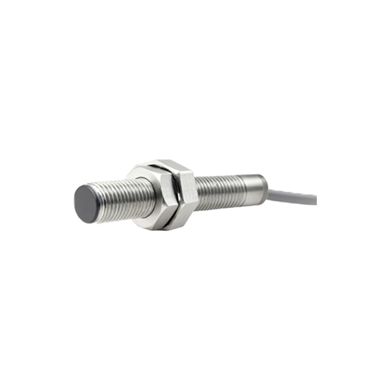
A cylinder proximity switch sensor, often an inductive or magnetic type, is mounted on the cylinder body. Its core function is to detect the presence of the piston (usually equipped with a permanent magnet ring) at a specific point in its stroke. The sensor generates a discrete electrical signal (ON/OFF) to the PLC or control system, confirming the cylinder's extended or retracted position. Incorrect adjustment leads to false signals, which can cause machine faults, sequence errors, or even safety hazards.
Pre-Adjustment Safety and Preparation
1. Lock Out/Tag Out (LOTO): Before any adjustment, ensure the machine is in a safe state. Follow proper LOTO procedures to isolate energy sources (electrical, pneumatic, hydraulic).
2. Gather Tools: Typically, only a small flat-head or hex key is needed to adjust the sensor's position. Have the machine manual and sensor datasheet available.
3. Initial Inspection: Visually check the sensor and its mounting bracket for damage. Ensure the magnet ring on the piston is correctly installed and not damaged.
Step-by-Step Adjustment Procedure
Step 1: Manual Actuation for Reference Points
Manually cycle the cylinder to its full stroke using the system's manual controls (if safe) or by carefully applying air pressure. Observe and mentally note the exact physical locations where the piston reaches its fully retracted and fully extended positions. This gives you the target zones for sensor activation.
Step 2: Loosen the Sensor Mounting
Locate the locking screw on the sensor's mounting clamp. Loosen it just enough to allow the sensor to slide along the cylinder's axis, but not so loose that it moves freely.
Step 3: Positioning for End-of-Stroke Detection
For Retracted Position Detection: Slide the sensor along the cylinder body until it is aligned with the position of the piston's magnet ring when the cylinder is fully retracted.
For Extended Position Detection: Slide the sensor to align with the magnet ring's location when the cylinder is fully extended.
For cylinders requiring detection at an intermediate position, you will need to stroke the cylinder to that specific point first.
Step 4: Fine-Tuning and Signal Verification
This is the most critical phase. Slowly move the sensor in tiny increments.
1. Activate the Sensor Zone: Position the sensor so that its sensing face is within the operational range of the magnet. Most sensors have an LED indicator.
2. Find the "Switch-On" Point: Move the sensor toward the magnet until the indicator LED just turns ON. Note this position.
3. Find the "Switch-Off" Point: Continue moving the sensor in the same direction until the LED just turns OFF. The optimal position is typically in the middle of this ON range.
4. Check Both Extremes: Cycle the cylinder manually again. Verify that the LED illuminates brightly and consistently only when the piston is within the desired detection zone (e.g., fully retracted). It must be OFF when the piston is away from that zone.
Step 5: Securing and Final Validation
1. Tighten Securely: While holding the sensor in its optimized position, firmly tighten the mounting screw. Avoid over-tightening, which may damage the clamp or affect the sensor housing.
2. Operational Test: Remove LOTO devices and initiate a full automatic machine cycle at slow speed. Monitor the sensor's feedback signal on the HMI or diagnostic lights. The signal must be stable and jitter-free at the correct moment in the cycle.
3. Stress Test: Run several consecutive cycles. Check for consistency. Environmental factors like vibration or temperature shifts can sometimes affect a borderline adjustment.
Troubleshooting Common Issues
No Signal: Check power supply, wiring, and connector. Verify the magnet ring is present and oriented correctly (North/South pole facing the sensor).
Intermittent Signal: The sensor is likely at the very edge of its sensing range. Re-adjust to the center of the ON range. Check for excessive cylinder play or misalignment.
Constant ON Signal: The sensor may be damaged, or the sensing range is too broad. Ensure it is not detecting other nearby metal objects or adjacent cylinders' magnet rings.
Best Practices for Long-Term Reliability
Use sensors with adjustable sensing distance if precise positioning is challenging.
Employ