Electromagnetic proximity switch sensors are essential components in modern industrial automation, offering non-contact detection of metallic objects. Understanding their wiring diagrams is crucial for ensuring reliable operation, safety, and system integration. This guide provides a comprehensive overview of wiring practices for these sensors, tailored for engineers and technicians in the electrical and automation fields.
Electromagnetic proximity sensors operate on the principle of electromagnetic induction. When a metallic target enters the sensor's detection range, it induces eddy currents in the sensor's oscillator coil, causing a change in oscillation amplitude. This change is detected by the sensor's circuitry, triggering a switching output. These sensors are widely used in applications such as position sensing, limit switching, and object counting in machinery, conveyor systems, and robotic assemblies.
A typical electromagnetic proximity switch sensor has three or four terminals, depending on its design (e.g., NPN or PNP output types). The standard wiring configuration includes:
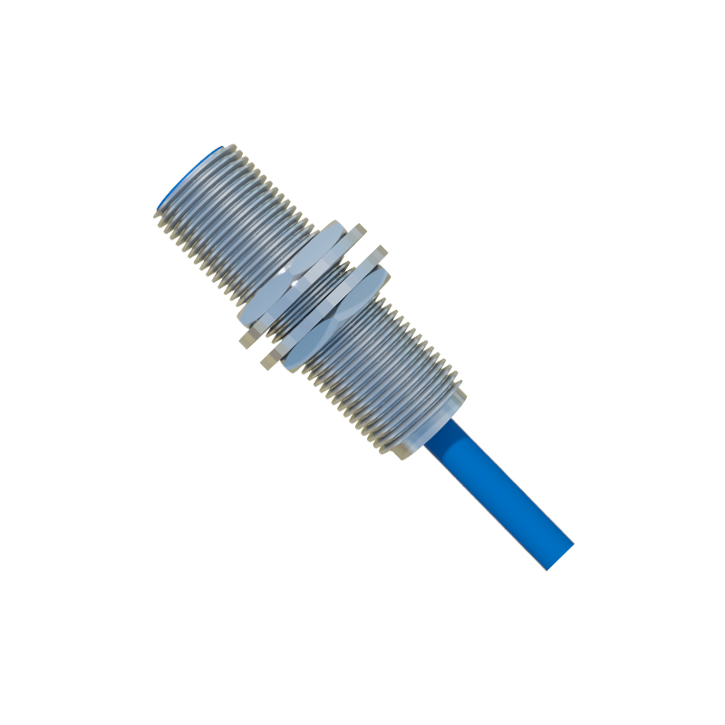
1. Power Supply Terminals: Usually labeled as V+ (positive) and V- (negative or ground). These connect to a DC power source, commonly 10-30V DC, ensuring stable operation.
2. Output Terminal: This provides the switching signal (e.g., NO/NC contacts) to control external devices like PLCs, relays, or indicators.

3. Shield or Auxiliary Terminal: Some models include a shield wire for grounding to reduce electrical noise interference.
The wiring diagram varies based on the sensor type. For NPN sensors, the output switches the negative (ground) side of the load, while PNP sensors switch the positive side. In a basic setup, connect the V+ terminal to the positive DC supply and V- to the negative. The output wire links to the load (e.g., a PLC input module), with the load's other side connected to the opposite supply polarity. Always refer to the manufacturer's datasheet for specific voltage ratings and pin assignments.
Key considerations for wiring include:
- Polarity Protection: Incorrect polarity can damage the sensor. Use color-coded wires (e.g., brown for V+, blue for V-) to avoid mistakes.
- Load Compatibility: Ensure the sensor's output current and voltage match the load requirements. Overloading may cause failure.
- Noise Reduction: In industrial environments, electromagnetic interference can affect performance. Use shielded cables, ground the shield properly, and avoid routing wires near high-voltage lines or motors.
- Safety Measures: Install fuses or circuit breakers in the power line to protect against short circuits. Follow lockout-tagout procedures during maintenance.
For complex systems, integrate multiple sensors with PLCs or controllers. In such cases, wiring diagrams should detail daisy-chaining or star configurations, emphasizing isolation to prevent cross-talk. Testing is vital: after wiring, verify sensor response with a metallic target and check output signals using a multimeter or oscilloscope.
Common issues in wiring include loose connections, incorrect voltage, or environmental factors like moisture. Troubleshoot by inspecting connections, measuring supply voltage, and ensuring the target material (ferrous or non-ferrous metals) is within specifications. Regular maintenance, such as cleaning sensor faces and checking cable integrity, prolongs lifespan.
In summary, proper wiring of electromagnetic proximity switch sensors enhances system reliability and efficiency. By adhering to diagrams and best practices, engineers can mitigate risks and optimize automation processes. As technology evolves, newer sensors with integrated diagnostics or IO-Link capabilities may require updated wiring approaches, but the core principles remain consistent.