In the field of industrial automation and electrical engineering, proximity switch sensors are essential components for detecting the presence or absence of objects without physical contact. Among the various technical terms associated with these devices, "TE" is a common abbreviation that often appears in specifications and documentation. Understanding what TE stands for and its implications is crucial for engineers and technicians working with proximity sensors to ensure optimal performance and system integration.
TE typically stands for "Terminal" or "Terminal Connection" in the context of proximity switch sensors. This refers to the electrical terminals used for wiring the sensor into a control system, such as a PLC (Programmable Logic Controller) or relay. These terminals are critical points where power supply, output signals, and sometimes diagnostic functions are connected. In many sensor designs, TE may be labeled on the housing or in wiring diagrams to indicate the specific terminals for different functions, helping to prevent miswiring and potential damage.
The significance of TE lies in its role in the sensor's electrical interface. Proximity sensors, including inductive, capacitive, and magnetic types, rely on precise electrical connections to operate correctly. For instance, a typical three-wire DC proximity sensor might have terminals marked as TE1 for power supply positive, TE2 for output, and TE3 for power supply negative or ground. Proper identification and connection of these terminals ensure that the sensor can detect targets accurately and transmit signals reliably to downstream equipment. Misunderstanding TE could lead to installation errors, such as reversed polarity or short circuits, which may cause sensor failure or system downtime.
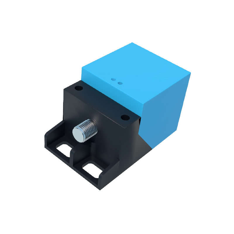
In addition to basic terminal functions, TE may also relate to "Terminal Emulation" in advanced sensor models, particularly those with programmable features or communication protocols like IO-Link. In such cases, TE refers to the configuration of terminal behavior through software, allowing users to customize output modes, switching delays, or diagnostic alerts without physically altering wiring. This enhances flexibility in automation setups, enabling sensors to adapt to varying operational requirements. For example, a sensor with TE emulation capabilities might be set to provide a pulsed output instead of a steady signal, useful in specific counting or timing applications.
When selecting or installing proximity switch sensors, engineers should consult manufacturer datasheets to interpret TE accurately, as its meaning can vary slightly between brands. Key considerations include voltage ratings, current capacity, and environmental factors like IP (Ingress Protection) ratings for terminal durability. Best practices involve using appropriate tools for termination, such as crimp connectors or screwdrivers, and following ESD (Electrostatic Discharge) precautions to protect sensitive electronic components. Regular maintenance, including checking terminal tightness and insulation, helps prevent connectivity issues over time.
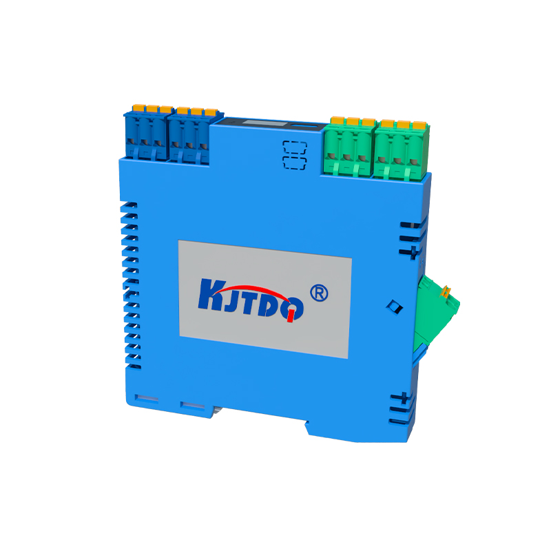
Overall, TE in proximity switch sensors underscores the importance of electrical interfaces in industrial applications. By grasping this term, professionals can improve installation accuracy, troubleshoot effectively, and leverage sensor capabilities for efficient automation. As technology evolves, with trends toward miniaturization and smart sensors, understanding fundamental aspects like TE remains vital for ensuring reliable and safe operations in manufacturing, robotics, and beyond.