Proper installation direction is a critical, yet often overlooked, factor in maximizing the performance and accuracy of a laser displacement sensor. The orientation of the sensor relative to the target surface and its environment directly influences measurement stability, signal integrity, and long-term reliability. This guide outlines the core principles and practical considerations for selecting the optimal installation direction.
The fundamental consideration is the angle of incidence—the angle between the sensor's laser beam and a line perpendicular (normal) to the target surface. For most standard diffuse reflection sensors, the ideal condition is to install the sensor so that its laser beam strikes the target at a 90-degree angle (perpendicular incidence). This configuration ensures the maximum amount of reflected light returns to the sensor's receiver, providing the strongest possible signal and highest accuracy. Deviating from this perpendicular angle reduces the intensity of the returned light, potentially leading to unstable readings or measurement dropout, especially on dark, rough, or low-reflectivity surfaces.
However, real-world applications often present challenges that necessitate deviations from the ideal perpendicular setup. A common scenario involves measuring shiny, mirror-like, or specular surfaces. If a sensor is mounted perpendicular to such a surface, the laser beam reflects directly away from the sensor's receiver, resulting in no signal. The standard solution is to employ a triangulation principle by mounting the sensor at a deliberate oblique angle. This ensures the reflected beam from a specular surface is directed into the receiver. The specific angle (often between 10 to 30 degrees from perpendicular) depends on the sensor's internal design and must be determined through testing or by consulting the manufacturer's specifications.
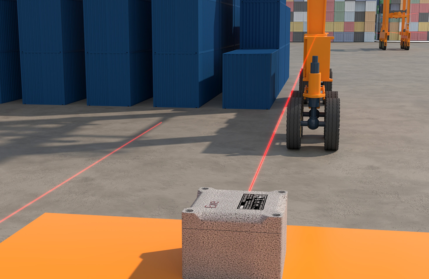
Environmental factors heavily influence installation direction. The primary goal is to minimize the impact of ambient light, dust, steam, oil mist, or vibrations. To combat ambient light interference from overhead lighting or sunlight, avoid mounting the sensor in a way that its receiver "looks" directly at a light source. Positioning the sensor's beam path vertically (up or down) can often reduce side-light intrusion. In dirty or misty environments, mounting the sensor horizontally or with the laser pointing slightly downward can help prevent the accumulation of contaminants on the sensor's front lens, which would attenuate the laser beam. If vibration is present, ensure the sensor is rigidly mounted and oriented so that the axis of vibration does not align with the sensitive measurement axis of the sensor.
The nature of the target object's movement also dictates orientation. For objects moving on a conveyor, the sensor is typically mounted above, pointing down. It is crucial to ensure the laser spot remains on the target throughout its travel path, considering possible object sway or misalignment. For measuring thickness of transparent materials (e.g., glass, plastic film), two sensors must be used in an opposing configuration, precisely aligned so their laser beams are collinear. Any angular misalignment between the two sensors will introduce a cosine error into the thickness calculation.
Mechanical stability is paramount. The sensor must be mounted on a solid, non-flexing bracket or fixture using appropriate hardware. The mounting should isolate the sensor from machine vibrations. Furthermore, consider cable routing; the sensor's cable should be secured in a way that minimizes stress on the connector, which is a common point of failure. Avoid creating loops in the cable that can snag or act as an antenna for electrical noise.
A systematic approach is recommended. First, clearly define the measurement task: target material, surface finish, required accuracy, and environmental conditions. Second, consult the sensor's user manual for specific installation guidelines, valid measurement ranges, and beam spot diagrams. Third, perform a physical test before final installation. Use the sensor in a temporary setup to observe signal strength indicators (often available via controller software) while simulating real operating conditions. This test will reveal issues with angle, reflectivity, or environmental light. Finally, after securing the sensor in its final position, verify the measurement over an extended period to ensure long-term stability.
In summary, there is no single "correct" direction for all applications. The optimal laser displacement sensor installation direction is a compromise between the ideal perpendicular incidence, the physical constraints of the target and environment, and the specific measurement principle of the sensor. Careful planning, understanding the sensor's operating principle, and thorough on-site testing are the keys to a successful installation that delivers reliable, high-precision data. Ignoring these directional factors can lead to persistent measurement errors, unreliable operation, and ultimately, system failure.