Ultrasonic proximity sensors are pivotal components in modern industrial automation, providing reliable non-contact detection and distance measurement. An image of such a sensor is more than just a picture; it is a visual guide to its functionality, construction, and integration. Typically, these images showcase a compact, cylindrical or rectangular housing, often made of rugged materials like nickel-plated brass, stainless steel, or high-grade plastics to withstand harsh industrial environments. The front face features the ultrasonic transducer, a critical element visible as a metallic or ceramic disc. This transducer acts as both speaker and microphone, emitting high-frequency sound waves (typically between 40 kHz to 400 kHz) and receiving their echoes.
A detailed image reveals key design aspects. Many sensors have a threaded barrel for easy mounting, with clear markings for the sensing range. LED indicators for power and output status are often visible, providing immediate diagnostic information. The image might also show the connection method, whether it's a pre-wired cable or a quick-disconnect plug, typically with 3 to 4 pins (V+, 0V, Output, and sometimes a second output or analog signal). The sensing face is usually flat and unobstructed, designed to direct the ultrasonic cone effectively. Some advanced models feature built-in temperature compensation components, which are not visually distinct but are crucial for maintaining accuracy as sound speed varies with air temperature.
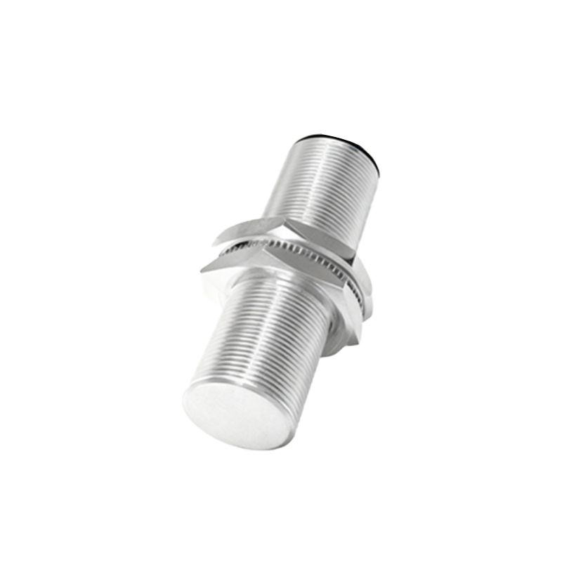
Interpreting the sensing pattern from an image is vital. While the ultrasonic beam itself is invisible, technical diagrams often overlay a cone-shaped pattern emanating from the transducer. This cone angle, which can range from 5 to 30 degrees depending on the model, defines the detection area. A narrower beam is suitable for precise detection of small objects or for use in tight spaces, while a wider beam covers a larger area. The effective sensing range, from a few centimeters up to several meters, is another key specification often implied by the sensor's size and design in the image.
The output type is a fundamental characteristic. Images of sensors with discrete outputs (PNP/NPN) look identical to those with analog (0-10V, 4-20mA) or IO-Link digital outputs. This highlights the importance of referring to the part number and datasheet. The housing might bear labels indicating the specific type, such as "NO/NC selectable" or "Analog." Furthermore, images of washdown or hygienic models show smoother surfaces, sealed connectors (often with an IP67, IP68, or IP69K rating), and sometimes a Teflon-coated face to resist chemical buildup, which is essential for food and beverage or pharmaceutical applications.
In practical application photos, the sensor is shown installed on a machine—perhaps detecting the presence of a cardboard box on a conveyor, controlling the fill level in a silo, or ensuring robot safety by monitoring a perimeter. These contextual images demonstrate proper mounting: ensuring the target object is within the beam cone, avoiding mounting too close to hard, reflective surfaces at the same distance as the target (which can cause false echoes), and angling the sensor slightly if the target surface is highly absorbent. Understanding these nuances from visual examples prevents common installation errors.
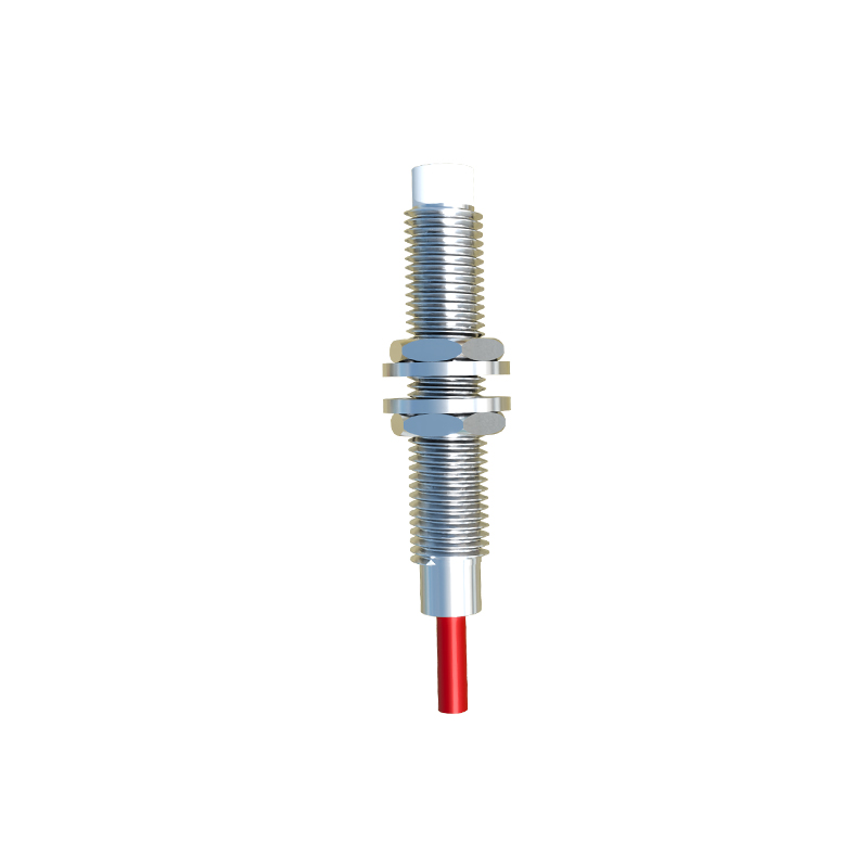
In conclusion, a well-analyzed image of an ultrasonic proximity sensor provides immense practical value. It allows engineers and technicians to quickly identify the sensor type, estimate its capabilities, plan its integration, and anticipate installation requirements. By learning to read the visual cues—the housing material, transducer size, connector type, and any special markings—professionals can select and deploy these versatile sensors more effectively, ensuring robust and efficient operation in diverse automation and control systems.