Inductive proximity sensors are essential components in modern industrial automation, offering non-contact detection of metallic objects. The P68 series, known for its robust construction and high reliability, is widely used in harsh environments such as manufacturing lines, material handling systems, and heavy machinery. Proper installation is critical to ensure optimal performance, longevity, and safety. This guide provides a comprehensive overview of the installation process for P68 inductive proximity sensors, adhering to industry standards and best practices.
Before installation, verify the sensor specifications match the application requirements. Check the operating voltage (typically 10-30V DC or 20-250V AC), output type (PNP/NPN, NO/NC), sensing range, and housing material (often stainless steel or nickel-plated brass for P68). Ensure the environment is free from excessive dust, moisture, or chemical exposure beyond the sensor's IP68 rating, which guarantees protection against dust ingress and prolonged immersion in water.
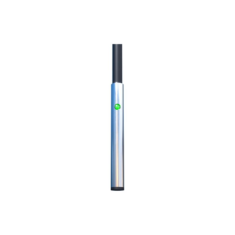
Mounting the sensor requires careful attention to positioning. For flush-mountable P68 sensors, install them in metal brackets so the sensing face is aligned with the surface. This minimizes interference from surrounding metals. Non-flush models should be mounted with adequate clearance—typically 1-2 times the sensor diameter—from adjacent metallic objects to prevent false triggers. Use appropriate tools to secure the sensor, avoiding over-tightening that could damage the housing or threads. The mounting torque should not exceed the manufacturer's specification, usually around 15-20 Nm for standard P68 units.
Wiring is a crucial step in the installation process. First, disconnect power to the circuit to prevent electrical hazards. Refer to the sensor's datasheet for wiring diagrams: typically, brown wire connects to positive voltage, blue to negative, and black (or white) to the load output. For AC models, ensure correct phase connections. Use shielded cables in environments with high electromagnetic interference (EMI), grounding the shield at the controller end only. Secure connections with crimp terminals or connectors rated for IP68 if the cable entry point is exposed. After wiring, apply a suitable sealant or cable gland to maintain the IP68 integrity, especially in wet or dusty conditions.
Alignment and testing are vital for functionality. Position the sensor so the target object approaches within the specified sensing range, typically 2-15 mm for P68 models, depending on size and material. Avoid angular misalignment; the target should move perpendicular to the sensing face for consistent detection. Once installed, power the system and test with the target metal. Use a multimeter or PLC to verify the output signal switches correctly. Adjust the mounting if the sensor fails to detect or shows erratic behavior. For applications involving fast-moving targets, consider the sensor's response time (often 0.5-1 ms) to ensure it keeps pace with the operation.
Maintenance and troubleshooting tips include regular inspections for physical damage, corrosion, or loose connections. In IP68-rated environments, clean the sensing face periodically with a soft cloth to remove debris that could reduce sensitivity. If the sensor malfunctions, check power supply stability, wiring integrity, and environmental factors like temperature extremes. Replace the sensor if it shows signs of internal failure, such as inconsistent output or no response. Always follow lockout-tagout procedures during maintenance to ensure safety.
In summary, installing a P68 inductive proximity sensor involves precise mounting, correct wiring, and thorough testing. By adhering to these guidelines, engineers can enhance system reliability, reduce downtime, and extend sensor life in demanding industrial settings. For specific applications, consult the manufacturer's documentation and local electrical codes to ensure compliance.