Capacitive proximity sensors are widely used in industrial automation for detecting both metallic and non-metallic objects, including liquids, powders, and plastics. Proper wiring is crucial to ensure reliable operation, safety, and longevity of these sensors. This guide provides a comprehensive overview of wiring practices for capacitive proximity sensors, covering key principles, connection methods, and troubleshooting tips.
Capacitive proximity sensors operate by generating an electrostatic field. When an object enters this field, it alters the capacitance, triggering the sensor's output. These sensors typically have three or four wires, depending on the design and functionality. The most common configurations include DC three-wire (NPN or PNP) and AC/DC two-wire models. For industrial applications, three-wire DC sensors are prevalent due to their stable performance and compatibility with programmable logic controllers (PLCs).
Wiring a three-wire capacitive proximity sensor involves connecting the brown wire (usually positive) to the DC power supply's positive terminal, the blue wire (negative) to the common ground, and the black wire (output) to the load, such as a PLC input module or relay. In NPN sensors, the output switches the negative side, while PNP sensors switch the positive side. It is essential to verify the sensor's specifications—including voltage range (commonly 10-30V DC), current rating, and output type—before installation. Always use shielded cables to minimize electromagnetic interference (EMI), especially in environments with high-frequency noise from motors or inverters. Ground the shield at one end to prevent ground loops.
For two-wire AC/DC sensors, wiring is simpler: one wire connects to the power source, and the other to the load. However, these sensors may have higher leakage currents, which can cause residual voltage issues. To avoid false triggering, consider using a bypass resistor or selecting sensors with low leakage current. Ensure the load impedance matches the sensor's requirements to prevent malfunction.
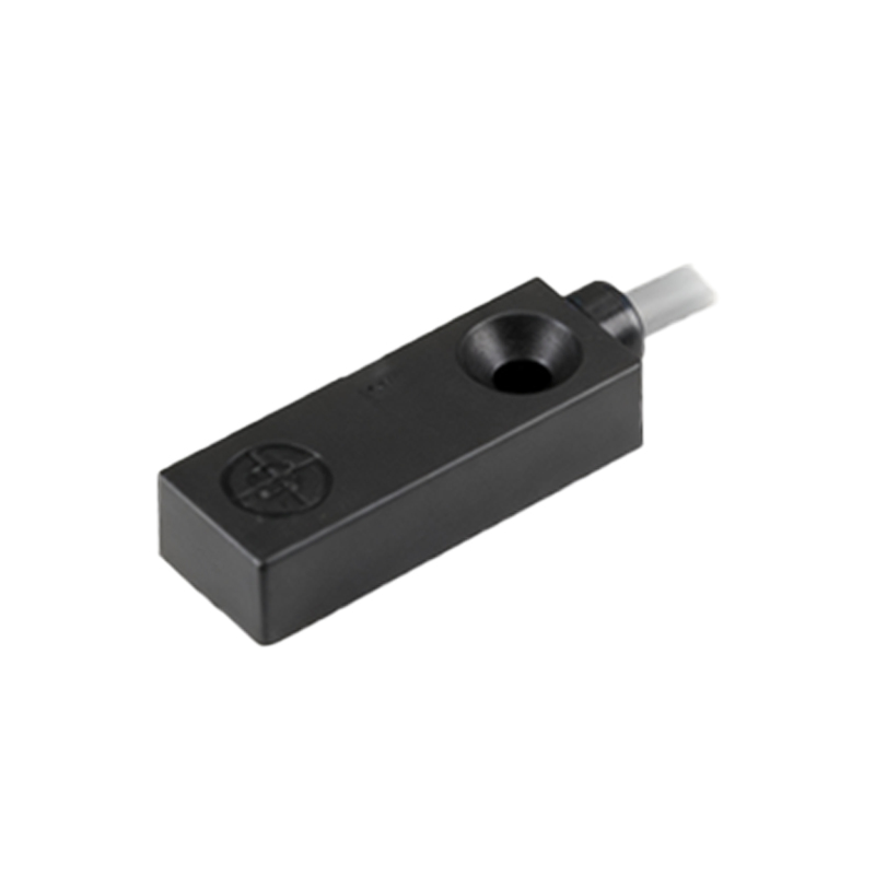
Mounting and environmental factors also impact wiring effectiveness. Keep sensor cables away from high-voltage lines and avoid parallel routing with power cables to reduce crosstalk. In harsh conditions, such as areas with moisture or dust, use IP-rated connectors and conduits for protection. Regularly inspect connections for corrosion or loose terminals, as these can lead to intermittent failures.
Troubleshooting common wiring problems involves checking power supply stability, verifying polarity, and measuring output signals with a multimeter. If a sensor fails to detect objects, confirm the sensing distance and adjust the sensitivity potentiometer if available. For false triggers, examine nearby objects or materials that might influence the electrostatic field.
In summary, correct wiring of capacitive proximity sensors enhances system reliability and safety. Adhering to manufacturer guidelines, implementing proper shielding, and considering environmental factors are key to optimal performance. As industrial automation evolves, understanding these wiring fundamentals remains essential for engineers and technicians.