In the realm of industrial automation, control systems, and machine design, the proximity sensor is a fundamental component. Creating an accurate and informative drawing of a proximity sensor is a critical skill for electrical engineers, designers, and drafters. This guide outlines the systematic process for drafting a proximity sensor, adhering to standard engineering practices and conventions.
The first step is to define the purpose and context of the drawing. Are you creating a detailed part drawing for manufacturing, a schematic symbol for a circuit diagram, or a representation within a P&ID (Piping and Instrumentation Diagram) or a machine layout? The objective dictates the level of detail and the drawing standards to follow. For a general component representation, we will focus on a combination of a schematic symbol and a simplified dimensional outline.
1. Schematic Symbol Representation:
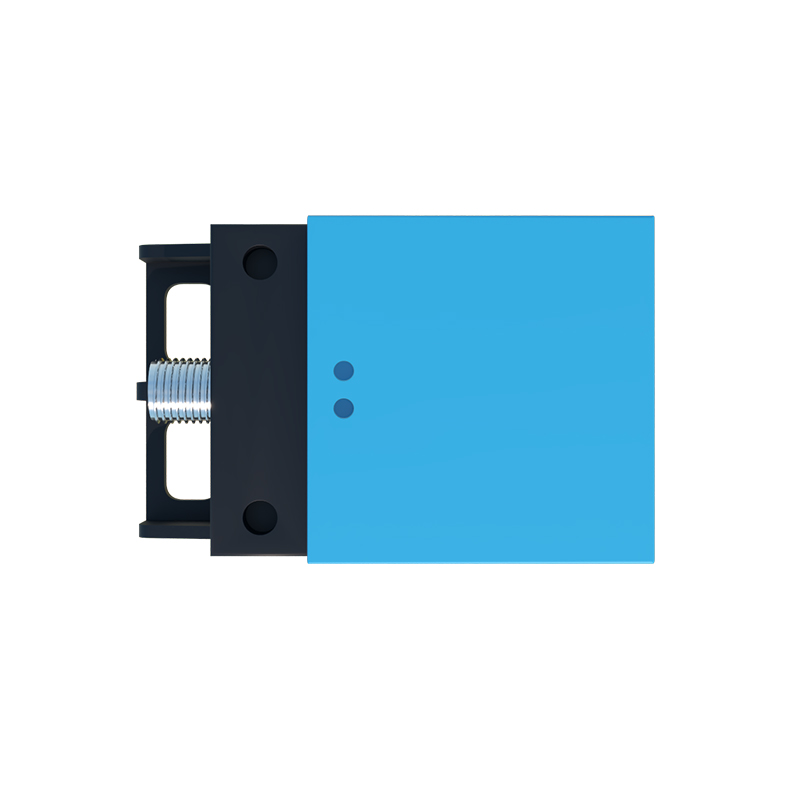
In electrical schematics, proximity sensors are represented by standardized symbols defined by standards such as IEC 60617 or ANSI/IEEE Std 315. The most common types are inductive and capacitive sensors.
Inductive Proximity Sensor: This symbol resembles a coil or inductor (representing the oscillator circuit) housed within a diamond shape, which is the standard symbol for a sensor or transducer. Two parallel lines are often drawn close to the flat sensing face of the diamond to indicate the "active" sensing area. The electrical connections are shown as lines extending from the symbol, typically labeled as +V (brown wire), 0V (blue wire), and the output signal (black wire for NPN/PNP switching output). A dashed line or an arrow pointing towards the sensing face can be added to represent the magnetic or electromagnetic field.
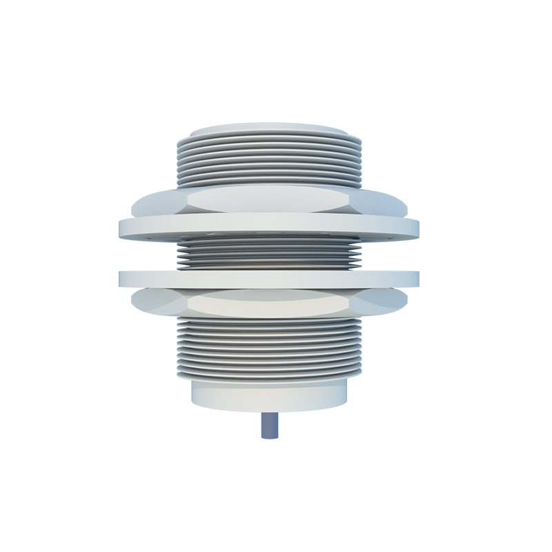
Capacitive Proximity Sensor: The symbol is similar but often includes two parallel plates inside or adjacent to the diamond, symbolizing the capacitive plates used for detection.
Output Type: It is crucial to denote the output configuration. An NPN (sinking) output is frequently indicated by the output line connecting to a downward-pointing arrow or the ground symbol. A PNP (sourcing) output may show the line connecting to the positive supply. The load (e.g., a PLC input, relay coil) is drawn connected appropriately to this output line.
2. Dimensional / Outline Drawing:
For integration into mechanical CAD layouts (like those in SolidWorks, AutoCAD, or Inventor), a 2D or 3D outline is necessary.
Start with the Body: Most cylindrical inductive sensors (e.g., M8, M12, M18, M30 threaded barrels) are drawn as a series of rectangles and cylinders. Begin with the main cylindrical body. Use precise dimensions from the manufacturer's datasheet: overall length, barrel diameter, and thread specifications.
Define the Sensing Face: Clearly mark the front face. This is usually a flat or slightly curved surface at one end of the cylinder. Indicate the nominal sensing distance (Sn) with a note or a dimension line. This distance is typically a few millimeters for standard sensors.
Add Mounting Details: Draw the hex nut or mounting bracket. For threaded barrels, include the thread length and the wrench flat dimensions. For rectangular block-style sensors, detail the mounting holes and their centers.
Cable or Connector: Depict the integral cable or the connector (e.g., M12 4-pin or 5-pin). For a cable, show it exiting from the rear of the sensor body. For a connector, draw the plug's outline.
Labeling and Annotations: Every professional drawing must include a title block, but for the component itself, add key annotations. These should include: Part Number/Model, Sensing Type (Inductive/Capacitive), Sensing Distance, Output Type (NPN/PNP NO/NC), Supply Voltage Range (e.g., 10-30V DC), and IP Rating (e.g., IP67) if relevant for the layout. Use leader lines to point to specific features.
3. Best Practices for Clarity:
Layers: Use different layers for the outline, dimensions, electrical connections, and annotations.
Line Weights: Employ thicker lines for the object outline and thinner lines for dimensions, hidden lines, and centerlines.
Scale: Always draw to scale. A 1:1 scale is ideal for component libraries, but adjust as needed for assembly drawings.
Cross-Section: For highly detailed part drawings, a cross-sectional view can illustrate internal components like the coil, ferrite core, oscillator IC, and housing, though this is often proprietary.
Software Tools: Utilize industry-standard CAD software for mechanical outlines and E-CAD software (like EPLAN,