Proximity sensors are indispensable components in modern industrial automation, providing non-contact detection of metallic or other objects. Understanding their wiring is fundamental to ensuring reliable system operation, safety, and optimal performance. This guide delves into the standard wiring configurations for common types of proximity sensors, focusing on practical application and key considerations.
The core principle behind inductive proximity sensors, the most prevalent type for metal detection, involves an oscillator circuit that generates a high-frequency electromagnetic field. When a metallic target enters this field, eddy currents are induced, causing a change in the oscillator's amplitude. This change is detected by a threshold circuit, which subsequently switches the output state. The wiring facilitates the power supply to this internal circuitry and provides the switched output signal to the control system, typically a Programmable Logic Controller (PLC).
Wiring configurations are primarily defined by the sensor's output type: 2-wire, 3-wire, or 4-wire. Each has distinct characteristics.
1. 2-Wire Proximity Sensors
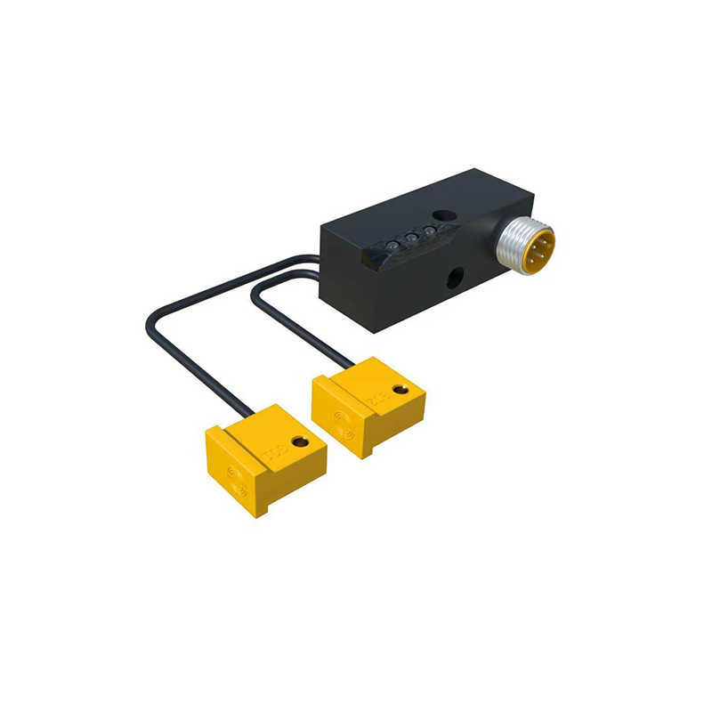
These are the simplest to wire, functionally similar to a mechanical switch. They connect in series with the load. The two wires serve as both the power supply path and the load switching path. When the sensor is inactive (no target detected), a small leakage current (often 1-2 mA) flows. Upon detection, the internal switch closes, allowing full load current to flow.
Wiring: One wire connects to the positive DC supply (for PNP types) or negative/ground (for NPN types), and the other wire connects to the load. The load's other terminal completes the circuit to the opposite supply rail. AC 2-wire sensors also exist.
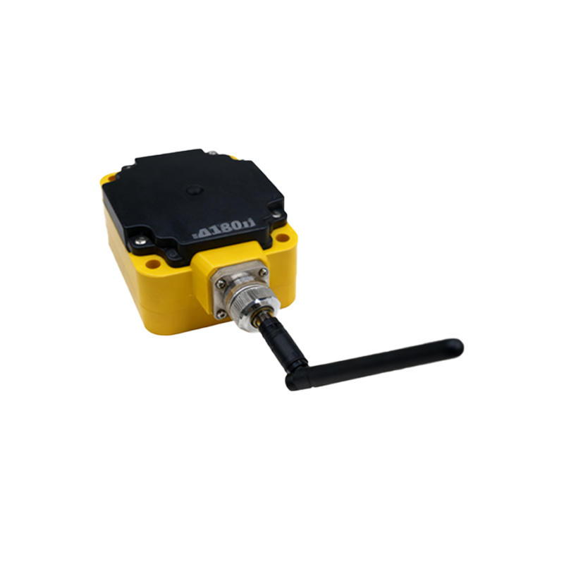
Considerations: Voltage drop across the sensor must be considered. They are simple but offer less electrical isolation and can be sensitive to leakage current requirements of the connected load.
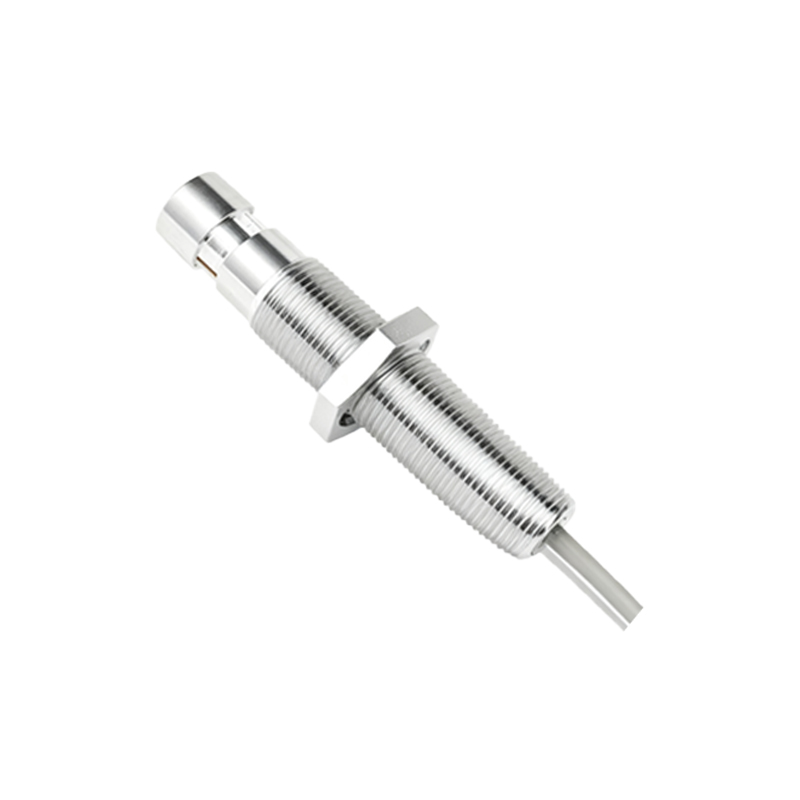
2. 3-Wire Proximity Sensors
This is the most common configuration in DC systems, offering superior performance. They have separate wires for power supply and the switched output, providing clear isolation.
Wiring: The three wires are typically Brown, Blue, and Black (standardized per IEC 60947-5-2).
Brown: Connects to the positive DC supply voltage (+V, e.g., 24VDC).
Blue: Connects to the power supply common (0V or ground).
Black: This is the output signal wire.
Output Types (Crucial Distinction):
PNP (Sourcing) Output: The Black wire sources current from the +V supply to the load. When activated, the output switch connects the Black wire to the internal +V. The load is connected between the Black wire and the common (Blue/0V).
NPN (Sinking) Output: The Black wire sinks current to the common/ground. When activated, the output switch connects the Black wire to the internal common (0V). The load is connected between the +V supply (Brown) and the Black wire.
Key Rule: For a PNP sensor, the load must be connected to the common/0V. For an NPN sensor, the load must be connected to the positive supply.
3. 4-Wire Proximity Sensors
These sensors essentially combine one PNP (normally open or closed) and one NPN (normally open or closed) output in a single housing, providing maximum flexibility. The four wires are usually Brown (+V), Blue (Common), Black (PNP output), and White (NPN output). This allows the same sensor to interface with both sourcing and sinking input cards without rewiring, by simply selecting the appropriate output wire.
Wiring to a PLC:
Most PLC digital input modules are designed as sinking (common positive) or sourcing (common negative). Matching the sensor output to the input type is essential.
A PNP (sourcing) sensor is compatible with a sinking PLC input.
An NPN (sinking) sensor is compatible with a sourcing PLC input.
Mismatching will result in no signal transfer. Always consult both the sensor and PLC module datasheets.
Critical Best Practices:
1. Power Supply: Use a stable, regulated DC power supply, typically 10-30VDC. Ripple and noise can cause erratic operation.
2. Shielded Cabling: In electrically noisy environments (near VFDs, motors, welding equipment), use shielded cables. Connect the shield to ground at the control panel end only, avoiding ground loops.
3. Fusing/