In the world of industrial automation and machinery control, proximity sensors are the silent sentinels. These non-contact devices detect the presence or absence of an object, playing a critical role in positioning, counting, and safety applications. From inductive sensors detecting metals to capacitive sensors for non-metallics and photoelectric sensors for long-range detection, their failure can halt production lines and cause significant downtime. Knowing how to properly replace a proximity sensor is an essential skill for any maintenance technician or plant engineer. This guide provides a systematic, safety-first approach to ensure a successful replacement and swift return to operation.
Before initiating any replacement, thorough preparation is paramount. First, consult the machine's electrical schematic and documentation to identify the exact sensor type, model number, and its role in the system. Is it a normally open (NO) or normally closed (NC) configuration? What is its operating voltage (e.g., 10-30V DC, 20-250V AC)? What is the sensing distance and required target material? Having a direct replacement or a fully compatible unit is crucial. Next, and most critically, implement a Lockout-Tagout (LOTO) procedure. Isolate the machine from all energy sources—electrical, pneumatic, and hydraulic. Verify zero energy state using a appropriately rated voltage tester. This non-negotiable step protects personnel from unexpected startups or electrical shock.
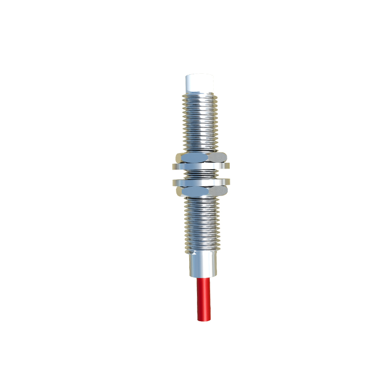
Gather your tools: screwdrivers, wrenches, wire strippers, crimping tools, and a multimeter. Ensure you have the correct replacement sensor, conduit fittings, and any necessary mating connectors or pre-wired cables.
The replacement process begins with the careful removal of the faulty sensor. If the sensor is housed in a junction box or connected via a quick-disconnect (M12 or M8 connector), simply unplug it. For hard-wired sensors, you must disconnect the wiring. Take a clear, well-lit photograph of the wiring connections before disconnecting a single wire. This is your best insurance against wiring errors later. Label each wire with tape markers according to its terminal number (e.g., Brown/+V, Blue/0V, Black/Output). Using a screwdriver, loosen the terminal screws and carefully remove the wires. Finally, unscrew or unclamp the sensor body from its mounting bracket. Inspect the mounting area for damage, corrosion, or misalignment that may have contributed to the failure.
Now, install the new sensor. Begin by mounting the sensor body securely in the exact same position and orientation as the old one. Pay close attention to the required sensing gap between the sensor face and the target object; even a few millimeters can affect performance. For threaded barrel sensors, use a lock nut to prevent vibration from loosening it. Next, proceed with wiring. If using a connector, simply mate it. For hard-wired connections, refer to your photograph and labels. Typically, for a 3-wire DC sensor: Brown wire to positive DC supply (+V), Blue wire to common negative (0V), and Black (or White) wire to the PLC input or load. Ensure wires are stripped to the correct length, terminals are tightened securely, and no stray strands are present. For metal-bodied sensors, ensure the ground wire (if present, often green/yellow) is properly connected to earth ground.
With wiring complete, do not immediately restore power. First, perform a visual and mechanical inspection. Check that all connections are tight, the sensor is firmly mounted, and no tools or debris are left in the panel. Slowly restore power following your site's energization procedures. The sensor's LED indicator (if equipped) will often provide immediate diagnostic feedback. A solid or blinking LED usually indicates power and a normal state (no target detected).
The final and most critical phase is testing and commissioning. Do not rely solely on the indicator LED. Introduce the target object (the specific metal, plastic, or material it is designed to sense) to the sensor's face. Observe the LED change and, more importantly, use your multimeter to verify the output signal switches correctly between voltage levels (e.g., from 0V to 24V for a PNP sourcing sensor). Then, initiate a controlled machine cycle, if possible in a manual or test mode. Verify the sensor triggers the correct machine sequence at the precise moment. Check for consistency over several cycles.
Common pitfalls to avoid include incorrect sensor type substitution (e.g., using an AC sensor on a DC circuit), wiring the output to the wrong polarity, ignoring environmental factors like washdown, excessive heat, or chip buildup that doomed the previous sensor, and failing to adjust the sensor or target position for optimal reliability.