Arduino laser sensors are widely used in industrial automation, robotics, and measurement systems due to their precision and reliability. As an electrical engineer, understanding how to implement and optimize code for these sensors is crucial for developing efficient and accurate projects. This guide provides a detailed overview of Arduino laser sensor code, covering setup, calibration, data processing, and troubleshooting, tailored to industry standards.
First, it's essential to select an appropriate laser sensor module compatible with Arduino. Common types include time-of-flight (ToF) sensors like the VL53L0X or analog/digital output sensors such as the GP2Y0A21YK. Each sensor has unique characteristics, so reviewing the datasheet is mandatory before coding. For instance, ToF sensors offer high accuracy for distance measurement, while analog sensors may require additional calibration for specific applications.
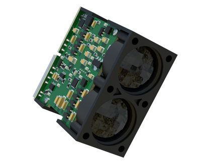
The basic setup involves connecting the sensor to the Arduino board. Typically, laser sensors use I2C, SPI, or analog pins. For an I2C-based sensor like the VL53L0X, connect the VCC to 5V, GND to ground, SDA to A4, and SCL to A5 on an Arduino Uno. Once wired, install the necessary libraries via the Arduino IDE, such as "Adafruit_VL53L0X" for ToF sensors. Begin the code by including the library and initializing the sensor in the setup() function. For example:
``cpp
#include
#include
Adafruit_VL53L0X lox = Adafruit_VL53L0X();
void setup() {
Serial.begin(9600);
if (!lox.begin()) {
Serial.println("Failed to boot sensor");
while(1);
}
}
`
This code initializes the sensor and checks for boot errors, ensuring reliable operation.
In the loop() function, read sensor data and process it based on your application. For distance measurement, use the sensor's readRange() method. Implement error handling to account for out-of-range values or interference. For example:
`cpp
void loop() {
VL53L0X_RangingMeasurementData_t measure;
lox.rangingTest(&measure, false);
if (measure.RangeStatus != 4) {
Serial.print("Distance (mm): ");
Serial.println(measure.RangeMilliMeter);
} else {
Serial.println("Out of range");
}
delay(100);
}
``
This code outputs distance in millimeters and handles errors by checking the RangeStatus. Calibration is vital for accuracy; use known reference points to adjust readings. For analog sensors, map the analog values to real-world units using the map() function in Arduino.
Advanced applications may involve filtering noise, integrating multiple sensors, or interfacing with other systems like PLCs. Implement median filters or moving averages in code to smooth data. For robotics, combine laser sensor data with motor control to enable obstacle avoidance. Always test code in real-world conditions to validate performance.
Troubleshooting common issues includes checking connections, updating libraries, and verifying power supply stability. Use serial monitoring to debug output and adjust delay times to prevent sensor overload. By following these practices, engineers can develop robust Arduino laser sensor systems for industrial use.