In industrial automation and control systems, proximity sensors are indispensable components for detecting the presence or absence of objects without physical contact. Among the various types available, two-wire and three-wire DC sensors are the most prevalent. While two-wire sensors offer simplicity in wiring by combining the power supply and load switching in a single loop, they come with inherent limitations such as higher residual current (leakage current) when off, voltage drop issues affecting the load, and sensitivity to electrical noise. These limitations can be problematic in precision applications or when interfacing with sensitive programmable logic controller (PLC) inputs. Consequently, there are scenarios where converting or effectively adapting a two-wire sensor to function within a three-wire system becomes a necessary engineering task. This article provides a technical overview of the principles, methods, and critical considerations for such a conversion.
Fundamentally, the core difference lies in the internal circuitry. A two-wire sensor is essentially a variable resistor that changes state in the presence of a target. It is connected in series with the load (e.g., a PLC input module). When active, it allows current to flow; when inactive, a small residual current still flows to power its internal electronics. A standard three-wire sensor, however, has separate wires for power supply positive (brown), power supply negative (blue), and the switched output signal (black). This design isolates the sensor's power circuit from the switching circuit, typically using a solid-state switch (like a transistor) to connect the output wire to either positive (PNP sourcing) or negative (NPN sinking) voltage. This eliminates residual current issues and provides a crisp, full-voltage signal.
Direct physical "conversion" of a two-wire sensor's housing into a three-wire device is not feasible without redesigning its internal electronics. Therefore, the practical approach involves using external interface components to adapt the two-wire sensor's behavior to a three-wire input. The most common and reliable method is employing an external relay or an interface module.
The relay method is straightforward. The two-wire sensor is wired in series with the coil of a standard industrial relay. The power supply (e.g., 24V DC) is connected to the sensor, and the sensor's other terminal connects to one side of the relay coil, with the coil's other side connected to the supply negative. When the sensor detects an object, it closes its internal switch, allowing sufficient current to energize the relay coil. The relay's mechanically linked contacts—now isolated from the sensor circuit—can then be used as a clean, three-wire-style output. For instance, a normally open (NO) contact on the relay can connect a PLC input (sinking) directly to 0V when activated, mimicking an NPN sensor behavior. This method effectively solves the leakage current problem, as the relay coil requires a minimum current to activate, which the sensor's off-state residual current cannot provide. It also handles voltage drop issues. The trade-offs include the addition of a physical component with moving parts (affecting switching speed and lifetime) and requiring space in the control panel.
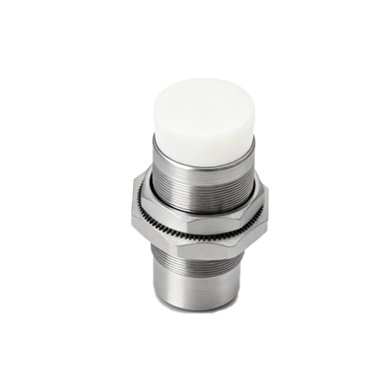
For a solid-state solution, a dedicated interface or conditioning module is preferable. These electronic modules are designed specifically for this purpose. They are connected between the two-wire sensor and the load. The module provides power to the sensor and monitors the current flow in the loop. Using internal circuitry, it distinguishes between the sensor's on-state current (e.g., >1.5mA) and its off-state residual current (e.g.,<0.8mA). When the on-state current is detected, the module activates a solid-state output transistor (PNP or NPN configurable) to provide a full-voltage, near-zero leakage output signal. These modules are fast, reliable, and compact, offering the benefits of a three-wire system without mechanical wear.
Several critical factors must be evaluated before implementing such a conversion. First, verify the electrical characteristics of the two-wire sensor: its operating voltage range, off-state leakage current, on-state voltage drop, and maximum switching current. Ensure the chosen interface (relay coil or module input) is compatible. Second, consider the load requirements. A PLC digital input typically has a specified "ON" current threshold and a maximum "OFF" current threshold. The converted system's off-state current must be below the PLC's OFF threshold to prevent false triggering. Third, always adhere to safety standards and wiring codes. Use proper fusing, ensure correct wire gauges, and implement protective measures like flyback diodes for relay coils or surge protection for long cable runs. Finally, while adaptation is practical for existing sensor inventories or legacy systems, for new installations, specifying a true three-wire sensor from the outset is often more cost-effective and elegant, providing better