Replacing a rectangular proximity switch sensor is a common yet critical task in industrial electrical maintenance. These robust, non-contact sensors are vital for position detection, object counting, and automation control in machinery. A failed sensor can halt production lines, making efficient and correct replacement essential. This guide provides a systematic, safety-first approach for engineers and technicians.
Pre-Replacement Preparation and Safety
Safety is paramount. Before any work begins, follow lockout/tagout (LOTO) procedures to isolate the machine or control panel from all energy sources—electrical, pneumatic, and hydraulic. Verify the power is off using a properly rated multimeter. Gather necessary tools: appropriate screwdrivers, wrenches, a multimeter, wire strippers/crimpers, and the correct replacement sensor. Crucially, obtain the sensor's datasheet or part number from the old unit or machine manual. Rectangular sensors vary significantly in specifications (e.g., sensing distance, output type [PNP/NPN], voltage rating, connection type). Installing an incorrect model can cause malfunction or damage.
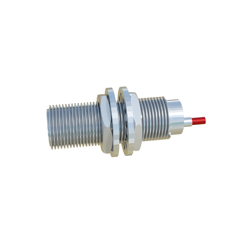
Step 1: Identification and Documentation
Locate the faulty sensor. Document the existing wiring configuration. Most rectangular proximity switches have a 3-wire or 4-wire connection (Brown/+V, Blue/0V, Black/Output, White/complementary output or shield). Use a digital camera to take clear photos of the wiring connections at the sensor's connector or terminal block. If wires are connected directly, carefully label each wire with tape according to its function (e.g., "Brn - 24V," "Blk - Output to PLC Inp.7"). This step prevents wiring errors during reinstallation.
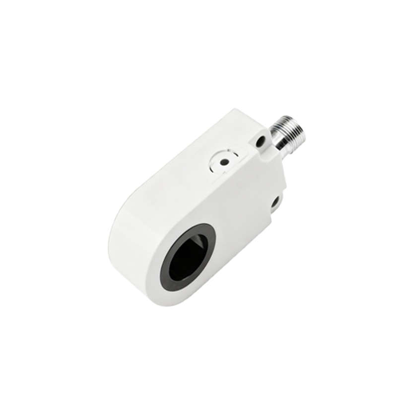
Step 2: Removal of the Old Sensor
First, disconnect the electrical connector. If it's a pre-molded connector, unplug it. If wires are terminated directly to the sensor's terminals, loosen the terminal screws and carefully disconnect the wires. Next, remove the sensor from its mounting bracket or housing. Rectangular sensors are typically held by one or two mounting nuts on the threaded barrel or by brackets with set screws. Use the correct wrench size to avoid rounding the nuts. Gently extract the sensor body from its location, noting its orientation and sensing face direction. The sensing face must be correctly aligned for the new unit.
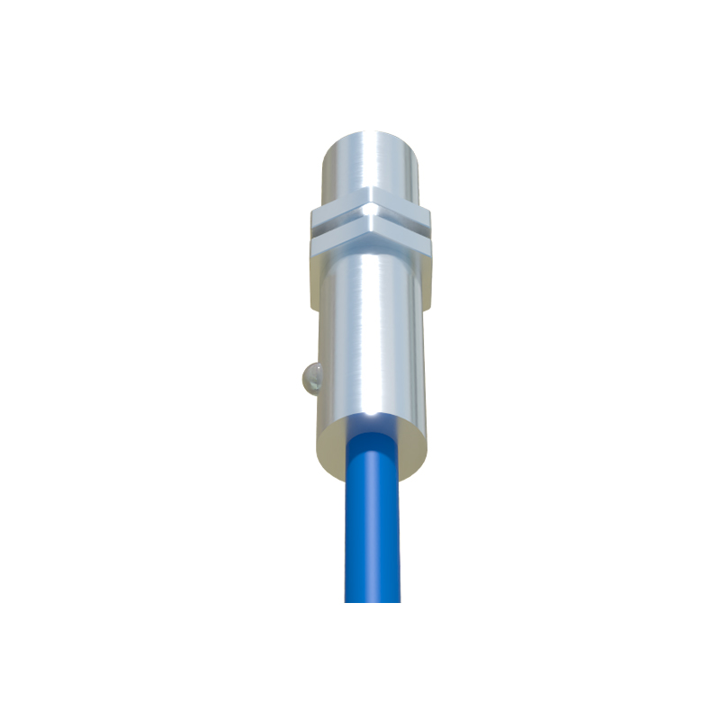
Step 3: Installation of the New Sensor
Compare the new sensor with the old one. Ensure the housing size, thread diameter (e.g., M12, M18, M30), and electrical specifications match. Insert the new sensor into the mounting location, replicating the exact orientation and depth of the old unit. For adjustable sensors, initially set it to the midpoint of its range. Hand-tighten the mounting nut(s) or bracket screws, but do not fully torque them yet. Reconnect the electrical wiring precisely as documented. Double-check that the Brown wire goes to the positive supply, Blue to the common/negative, and the output wire to the control input. Secure all connections firmly.
Step 4: Alignment and Functional Testing
Before applying power, ensure no personnel or objects are in the machine's danger zone. A critical step for inductive proximity sensors is setting the correct gap between the sensor's face and the target metal object (actuator). The required gap is usually specified in the datasheet (e.g., 2mm). Use a non-metallic feeler gauge to set this distance accurately. Once aligned, fully tighten the mounting nut to secure the position, being careful not to rotate the sensor body and alter the gap.
Now, restore power following your site's safety protocols. Do not immediately start the machine. First, perform a sensor functionality test. Use the multimeter to check voltage at the supply terminals. Then, manually introduce the target object (e.g., a metal plate) into the sensor's detection field. Observe the sensor's indicator LED (if present) and use the multimeter to verify the output signal switches correctly (e.g., from 0V to 24V for a PNP sensor). Confirm this signal change is registered at the PLC or controller input module by monitoring its diagnostic LEDs or software.
Step 5: Final Verification and Process Check
After successful bench testing, initiate a single-cycle or slow manual operation of the machine. Observe the sensor's operation through several cycles to ensure consistent and reliable detection. Check for any abnormal noise from the machinery that might indicate misalignment. Finally, document the replacement in the maintenance log, noting the date, part number, and any adjustments made.
Troubleshooting Tips
- No Output Signal: Verify power supply polarity and voltage. Check for wiring faults or a blown fuse.
- Intermittent Operation: Likely caused by loose wiring, improper