In the realm of industrial automation and precision measurement, laser sensors have become indispensable tools. Their ability to deliver non-contact, high-accuracy measurements of distance, position, and presence is well-documented. However, a critical yet often underutilized technique for enhancing their performance and overcoming specific application challenges is the strategic tilting of the sensor. This article delves into the engineering principles, practical benefits, and key considerations for implementing laser sensors at an angle, moving beyond the conventional perpendicular installation.
The fundamental operating principle of most laser triangulation sensors involves projecting a laser spot onto a target surface and using a receiver (typically a CCD or CMOS array) to detect the reflected light's position. When the sensor is mounted perpendicularly to the target, the measurement is straightforward. Introducing a tilt angle alters the geometry of this triangulation. This is not merely a mounting variation; it is a deliberate engineering choice to solve real-world problems.
One of the primary advantages of tilting a laser sensor is the mitigation of specular reflection issues. When measuring highly reflective surfaces like polished metal, glass, or glossy plastics, a perpendicular sensor often receives a blindingly intense, direct reflection that can saturate the receiver or cause erroneous readings. By tilting the sensor, the intense specular reflection is directed away from the receiver's lens. Instead, the sensor captures the diffuse scattered light from the surface texture or imperfections, providing a stable and reliable signal. This is crucial in industries such as semiconductor manufacturing or automotive painting.
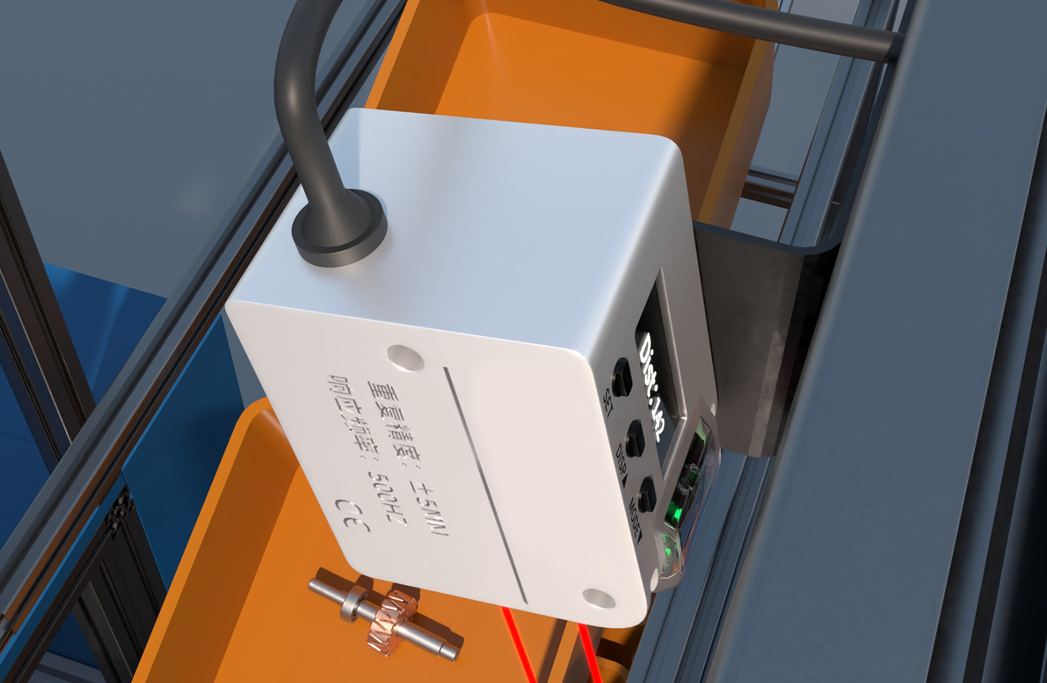
Similarly, for dark, matte, or light-absorbing surfaces, a perpendicular beam might not provide sufficient reflected light intensity for a robust measurement. A strategic tilt can increase the effective light collection by positioning the receiver to capture a greater portion of the scattered light, thereby improving signal-to-noise ratio and measurement stability on challenging materials like black rubber, carbon fiber, or dark textiles.
Tilted mounting is also a powerful solution for overcoming shadowing and occlusion. In complex geometries—such as measuring the depth of a groove, the step height on a PCB, or the profile of a weld seam—a perpendicular sensor's line-of-sight can be blocked by adjacent features. Angling the sensor provides a clear view into these recessed areas, enabling measurements that would otherwise be impossible. This is extensively used in 3D profiling and robotic guidance applications.
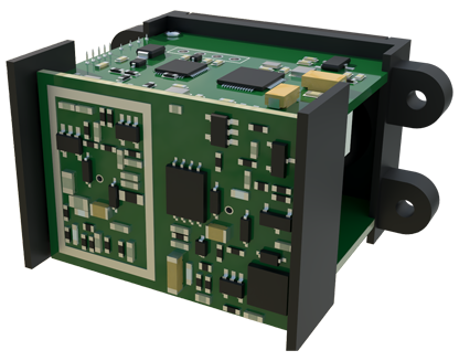
Furthermore, tilting can effectively avoid direct back-reflection from transparent objects. When measuring the thickness of glass or clear plastic, a perpendicular sensor might measure the reflection from the front surface, the back surface, or a confusing combination of both. Angling the sensor ensures that the primary reflection from the front surface is not received, allowing specialized sensors or algorithms to target the reflection from the second surface for accurate thickness gauging.
However, implementing a tilt angle is not without its trade-offs and requires careful calculation. The most significant effect is the introduction of cosine error. When a sensor measures a flat surface at an angle θ, the reported distance is the line-of-sight distance from the sensor head to the spot, not the true perpendicular distance. This must be corrected using trigonometry (True Distance = Measured Distance × cos(θ)). Modern sensors often have built-in software for this compensation, but the engineer must accurately input the tilt angle. Failure to correct for this results in a systematic measurement error.
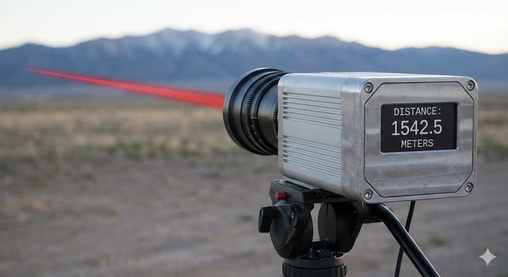
The tilt angle also affects the size and shape of the laser spot on the target. A perpendicular beam creates a circular spot. An angled beam creates an elliptical spot, which grows larger with increasing angle. This can reduce lateral resolution and potentially affect edge detection accuracy. The working distance and measurement range may also be effectively altered. Therefore, sensor selection must account for these geometric transformations. A sensor with a smaller inherent spot size and a larger measurement range provides more flexibility for tilted applications.
Best practices dictate a thorough pre-application analysis. Key steps include: defining the primary challenge (specular, low signal, occlusion), selecting an initial tilt angle (often between 5 to 30 degrees), calculating cosine error compensation, verifying spot size and intensity at the target through simulation or testing, and ensuring the mechanical mounting is rigid and vibration-free to maintain angle stability. Environmental factors like ambient light or dust should also be considered, as a tilted sensor might be more or less susceptible to them.
In conclusion, moving beyond the default perpendicular installation unlocks a higher tier of laser sensor application engineering. The deliberate tilting of a laser sensor is a sophisticated technique for conquering challenges posed by difficult surfaces, complex part geometries, and transparent materials. By understanding the underlying optical geometry, meticulously compensating for cosine error, and carefully selecting the appropriate hardware, engineers can significantly expand the capability and reliability of their measurement systems. This approach transforms the laser sensor from a standard tool into a versatile solution tailored for demanding industrial environments.