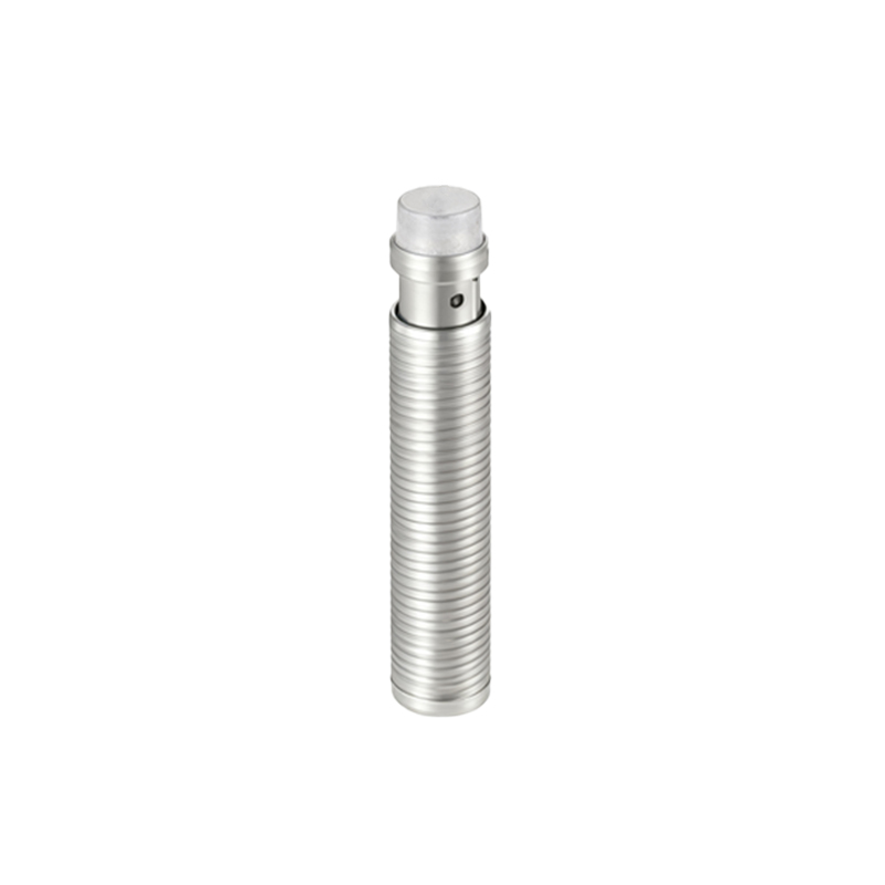
Infrared proximity sensors are widely used in various industries for object detection, distance measurement, and automation control. Understanding their working principle is essential for engineers and technicians involved in designing or maintaining systems that rely on non-contact sensing. This article provides a detailed explanation of the infrared proximity sensor principle with a focus on its operational diagram and key components.
At the core of an infrared proximity sensor is the use of infrared light, which is invisible to the human eye but can be detected by specialized electronic components. The sensor typically consists of two main parts: an infrared emitter (usually an IR LED) and an infrared receiver (such as a phototransistor or photodiode). The emitter emits infrared light in a specific wavelength range, often around 850 nm to 950 nm, which is directed toward the target area. When an object enters the sensor's detection range, the infrared light reflects off the object's surface and returns to the receiver. The receiver then converts the reflected light into an electrical signal, which is processed by the sensor's circuitry to determine the presence or distance of the object.
The working principle can be broken down into several stages, as illustrated in a typical diagram. First, the emitter circuit generates a modulated infrared signal to reduce interference from ambient light sources. This modulation involves pulsing the IR LED at a specific frequency, ensuring that the receiver only responds to signals matching that frequency. Next, the emitted light travels through the environment and strikes any object within its path. The amount of light reflected depends on factors like the object's material, color, and surface texture—for instance, light-colored or reflective surfaces tend to reflect more infrared light than dark or absorbent ones.
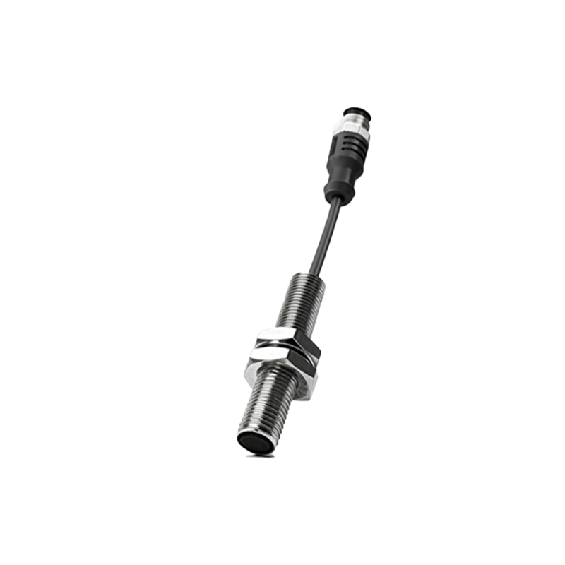
Upon reflection, the infrared light returns to the receiver component. In the diagram, the receiver is often shown connected to an amplifier and filter circuit that enhances the weak reflected signal while filtering out noise. The processed signal is then fed into a comparator or microcontroller, which compares it to a predefined threshold. If the signal strength exceeds the threshold, the sensor outputs a detection signal (e.g., a high or low voltage) to indicate the object's presence. For distance measurement, sensors may use triangulation or time-of-flight methods, where the angle or time delay of the reflected light is analyzed to calculate the object's proximity.
Key advantages of infrared proximity sensors include their non-contact nature, fast response time, and reliability in various environmental conditions. They are commonly applied in robotics for obstacle avoidance, in consumer electronics for touchless controls, and in industrial automation for part detection. However, limitations such as sensitivity to environmental factors (e.g., dust, fog, or direct sunlight) must be considered during design. Engineers often incorporate shielding, filters, or calibration techniques to mitigate these issues.
In summary, the infrared proximity sensor operates on the principle of emitting and detecting reflected infrared light, with its diagram highlighting the interplay between emitter, receiver, and signal processing stages. By mastering this principle, professionals can optimize sensor performance for diverse applications, ensuring accurate and efficient detection in modern technological systems.