Proximity sensors are critical components in modern industrial automation, robotics, and safety systems. These devices detect the presence or absence of objects without physical contact, relying on electromagnetic fields, capacitance, or inductive principles. A common maintenance task involves checking the sensor's resistance to ensure it operates within specified parameters. Using a digital multimeter (DMM) for this purpose is a straightforward yet essential skill for technicians and engineers. This guide provides a step-by-step approach to measuring proximity sensor resistance accurately, along with practical tips and safety considerations.
Before beginning any measurement, ensure the proximity sensor is disconnected from its power source and control circuitry. This prevents damage to the multimeter and avoids inaccurate readings due to external voltage or current. Identify the sensor type—inductive, capacitive, or magnetic—as this may influence resistance expectations. Most proximity sensors have two or three wires: typically, brown (power), blue (ground), and black (output). For resistance testing, focus on the power and ground terminals unless the manufacturer specifies otherwise.
Set your digital multimeter to the resistance measurement mode, denoted by the omega (Ω) symbol. Choose an appropriate range if your DMM is not auto-ranging; for proximity sensors, resistance values often fall between 100 ohms and 10 kilohms. Connect the multimeter's red probe to the sensor's power wire (usually brown) and the black probe to the ground wire (usually blue). Ensure firm contact to avoid fluctuating readings. The display will show the resistance in ohms. Compare this value with the sensor's datasheet specifications. A significant deviation—such as an open circuit (infinite resistance) or a short circuit (near-zero resistance)—indicates a faulty sensor that may require replacement.
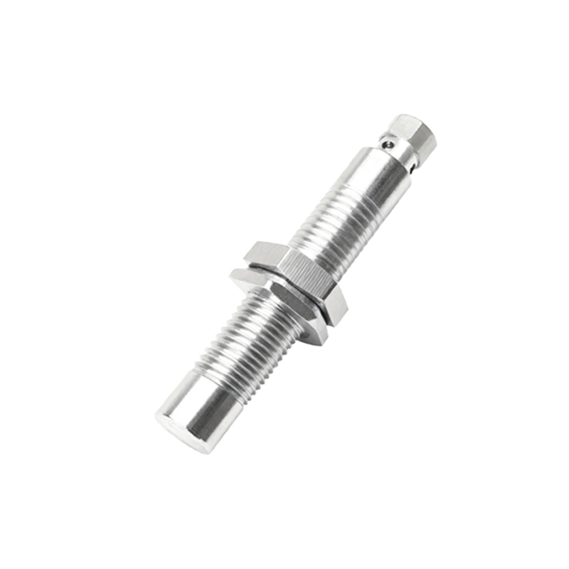
For three-wire sensors, additional checks might be needed. Measure resistance between the output wire (black) and ground, as well as between output and power, to assess internal switching mechanisms. Note that some active sensors contain electronic components that can affect resistance measurements; in such cases, consult the technical manual for specific testing procedures. Always perform measurements at room temperature, as extreme temperatures can alter resistance values.
Common issues during testing include poor probe contact, residual charge in the sensor, or environmental interference from nearby metal objects. To mitigate these, clean the sensor terminals, discharge any stored energy by briefly shorting the wires, and conduct tests in a controlled environment. Regularly calibrate your multimeter to maintain accuracy, and use high-quality probes with insulated grips for safety.
In summary, measuring proximity sensor resistance with a multimeter is a fundamental diagnostic technique. It helps identify wear, corrosion, or internal failures, ensuring system reliability and minimizing downtime. By following standardized procedures and adhering to safety protocols, professionals can efficiently troubleshoot and maintain sensor performance in various industrial applications.