In industrial automation and control systems, proximity sensors are indispensable components for non-contact detection of metallic or non-metallic objects. Among various types, the 3-wire proximity sensor is one of the most commonly used due to its reliability and straightforward integration. This article provides a detailed, step-by-step guide on how to correctly wire a 3-wire proximity sensor, covering essential principles, safety considerations, and practical troubleshooting tips.
Understanding the Basics of a 3-Wire Proximity Sensor
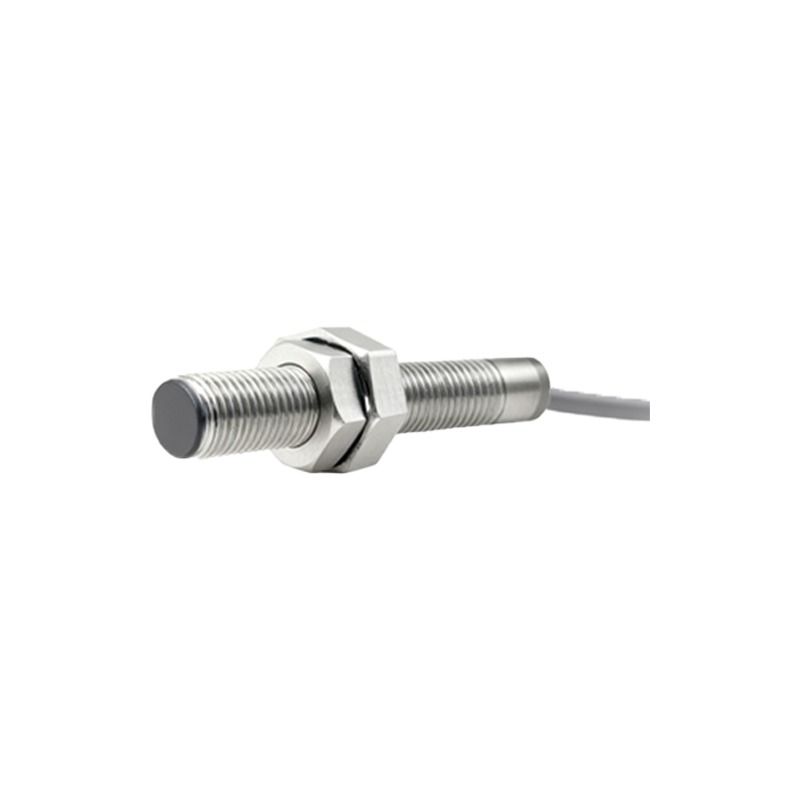
A typical 3-wire proximity sensor consists of three distinct wires: brown, blue, and black. These wires correspond to specific functions:
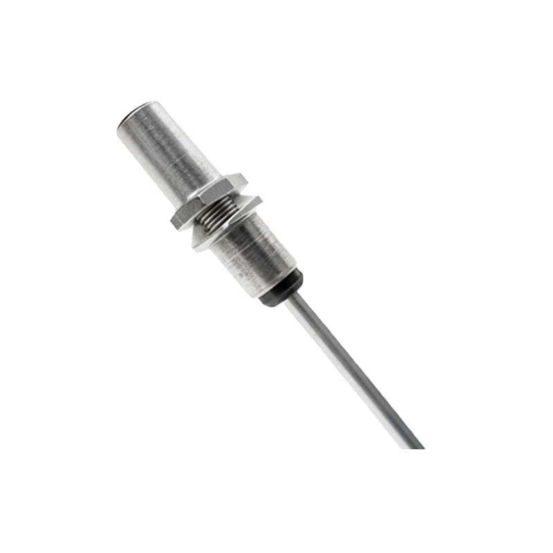
- Brown Wire: This is the positive supply voltage line (+V). It connects to the DC power source's positive terminal. The operating voltage range is usually specified on the sensor's datasheet, commonly 10-30V DC for many industrial models.
- Blue Wire: This is the negative or ground line (0V). It connects to the DC power source's negative terminal or the common ground of the control system.
- Black Wire: This is the output signal line. Depending on the sensor type, it provides either a normally open (NO) or normally closed (NC) output. When the sensor detects a target within its sensing range, the output switches state, sending a signal to the connected controller, such as a PLC (Programmable Logic Controller) or relay.
It is crucial to verify the sensor's specifications before wiring, as some sensors may have alternative wire colors or functions (e.g., white wire for output). Always refer to the manufacturer's documentation.
Step-by-Step Wiring Procedure
1. Power Supply Preparation: Ensure the DC power supply matches the sensor's voltage requirements. For instance, if the sensor operates at 12-24V DC, use a regulated power supply within that range. Disconnect power before starting any wiring work to prevent electrical hazards.
2. Connecting Power Wires:
- Connect the brown wire to the positive terminal of the DC power supply.
- Connect the blue wire to the negative terminal of the DC power supply.
Use appropriate wire gauges and secure connections with terminal blocks or connectors to avoid loose contacts, which can cause malfunction or damage.
3. Output Signal Connection:
- For a normally open (NO) sensor: Connect the black wire to the input module of the PLC or the coil terminal of a relay. The other side of the load should be connected to the positive supply, completing the circuit. When the sensor activates, it closes the switch, allowing current to flow to the load.
- For a normally closed (NC) sensor: The wiring is similar, but the output is inverted. The black wire connects to the load, and the circuit is normally closed, opening upon detection.
4. Shielding and Grounding: In environments with electrical noise (e.g., near motors or frequency drives), use shielded cables and connect the shield to a proper earth ground. This minimizes electromagnetic interference (EMI) and ensures stable sensor operation.
5. Polarity Check: Double-check all connections for correct polarity. Reversing the brown and blue wires can permanently damage the sensor.
Safety and Best Practices
- Always follow lockout/tagout (LOTO) procedures when working with electrical systems to ensure safety.
- Use overcurrent protection devices, such as fuses or circuit breakers, in the power line to protect the sensor from short circuits.
- Maintain adequate clearance between the sensor and metal objects to avoid false triggering. The sensing distance is specified by the manufacturer and should not be exceeded.
- For inductive proximity sensors (common for metal detection), ensure the target material is compatible (e.g., steel, aluminum). Different materials may affect sensing ranges.
Troubleshooting Common Issues
If the sensor fails to operate:
1. Verify power supply voltage with a multimeter. Low voltage can cause inconsistent performance.
2. Check wiring connections for looseness or corrosion.
3. Inspect the output load. Overloading the sensor (exceeding its current rating) can lead to failure. Most 3-wire sensors have a maximum output current, typically around 200mA.
4. Test the sensor by bringing a target within its sensing range. If the output LED (if equipped) lights up but no signal is received, the issue may lie in the connected controller or wiring.
In summary, wiring a 3-wire proximity sensor is a fundamental skill for electrical engineers and technicians. By adhering to standard procedures and safety guidelines, you can ensure reliable sensor integration into automation systems. Regular maintenance and verification further enhance longevity and performance, reducing downtime in industrial applications.