Proximity sensors are indispensable components in modern industrial automation, and the FX0N series stands out for its reliability and versatility. Proper wiring is not merely a procedural step; it is fundamental to ensuring sensor longevity, system accuracy, and operational safety. This guide provides a comprehensive overview of the wiring procedures for FX0N proximity sensors, adhering to industry best practices.
First and foremost, understanding the sensor's specifications is crucial. FX0N sensors are typically available in two primary output types: NPN (sinking) and PNP (sourcing). The wiring differs significantly between these two. An NPN sensor switches the negative (0V) line to the load, while a PNP sensor switches the positive (+V) line. Always verify the sensor's datasheet for its specific model number, operating voltage (commonly 10-30V DC), output configuration, and current rating before commencing any wiring work.
The basic wiring setup involves three core connections: power supply, load, and the sensor itself. For a standard 3-wire DC sensor:
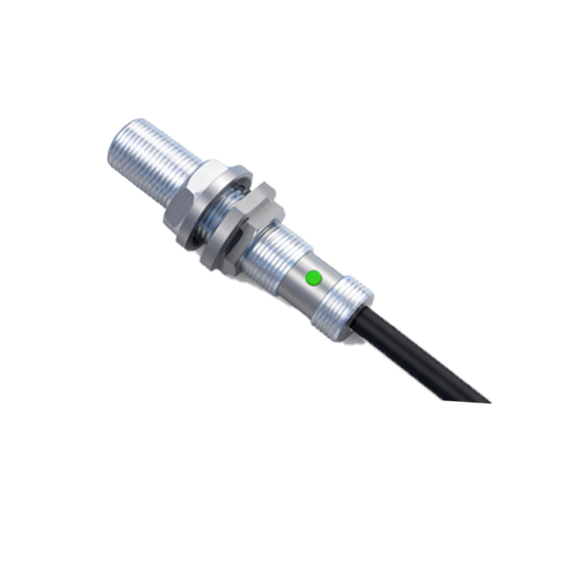
1. Brown Wire (or +V): This is the positive supply line. Connect it directly to the positive terminal of your DC power source (e.g., +24V).
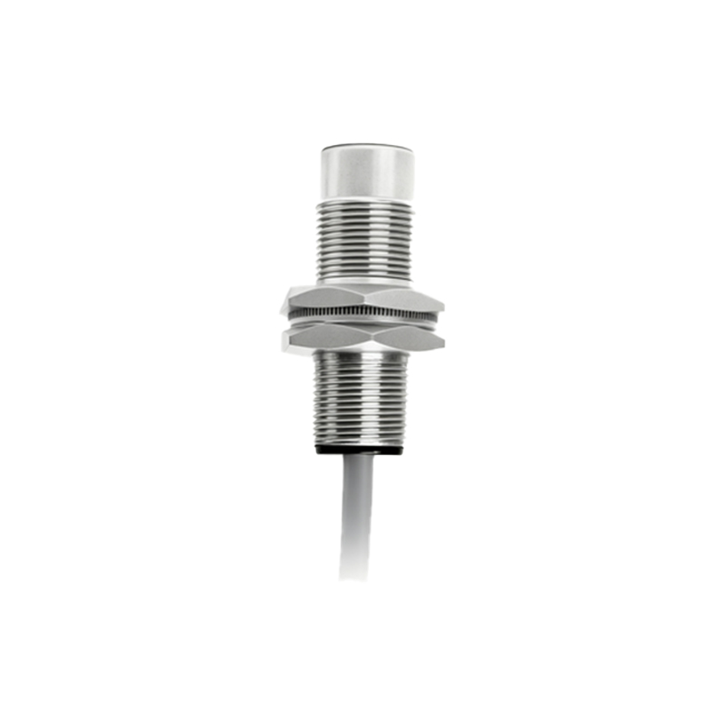
2. Blue Wire (or 0V): This is the negative or common line. Connect it directly to the negative terminal (0V) of the DC power source.
3. Black Wire (Output): This is the switched signal line. Its connection depends on the output type.
For an NPN sensor: The black wire outputs 0V when activated. Connect it to one terminal of your load (e.g., PLC input, relay coil). The other terminal of the load must be connected to the positive supply (+V).
For a PNP sensor: The black wire outputs +V when activated. Connect it to one terminal of your load. The other terminal of the load must be connected to the 0V (common) line.
A critical safety practice is to always implement a separate, fused power supply for sensors and control circuits. This isolation protects sensitive PLC inputs and other control devices from potential power surges originating in the main motor circuits. The fuse rating should be slightly above the total expected current draw of all connected sensors but below the current-carrying capacity of the wiring.
Shielding and grounding are paramount, especially in environments with significant electromagnetic interference (EMI) from motors, variable frequency drives (VFDs), or welding equipment. Use shielded cables for all sensor connections. Connect the cable's shield braid to a solid earth ground point at one end only, typically at the control panel's grounding busbar. Connecting both ends can create ground loops, which may introduce more noise than they prevent. Ensure the grounding point has a low impedance path to earth.
For wiring over longer distances, voltage drop becomes a concern. Using wires with an insufficient gauge can lead to the sensor receiving voltage below its operational minimum, causing erratic behavior. Consult voltage drop tables to select an appropriate wire gauge based on the current draw and the length of the run. It is often advisable to use a slightly thicker gauge than the minimum requirement.
When connecting to a Programmable Logic Controller (PLC), correct interfacing is essential. Most PLC digital input modules are designed to work with either NPN or PNP sensors, but their internal circuitry differs. Confirm your PLC input module's type (sinking or sourcing) to ensure compatibility with your chosen FX0N sensor. A mismatch will result in the input not being recognized. Some advanced FX0N models feature short-circuit protection, overload protection, and reverse polarity protection, adding an extra layer of security to your wiring installation.
Finally, after completing the wiring, a systematic checkout procedure is mandatory. Before energizing, visually inspect all connections for tightness and correct placement. Use a multimeter to check for short circuits between power lines and ground. Once powered, verify the sensor's indicator LED activates in the presence of a target and deactivates in its absence. Measure the output voltage with the sensor both ON and OFF to ensure it switches cleanly between the expected states.
In summary, meticulous wiring of FX0N proximity sensors—encompassing correct output type identification, proper shielding, adequate wire sizing, and safe power supply design—forms the bedrock of a robust and fail-safe automation system. Neglecting these principles can lead to intermittent faults, reduced equipment life, and costly downtime, while adherence guarantees precise, reliable detection for years of continuous operation.