Proper installation of proximity switch sensor mounting brackets is critical for ensuring reliable operation, accurate sensing, and long service life in industrial automation systems. A poorly mounted sensor can lead to false triggers, missed detections, physical damage, and costly downtime. This guide provides a detailed, step-by-step procedure for correctly installing these essential components, adhering to standard industry practices.
Before beginning any installation, the first and most crucial step is to consult the specific manufacturer's datasheet and installation manual for both the proximity sensor and the mounting bracket. Specifications for sensing distance, mounting clearances, material compatibility, and torque ratings can vary significantly between models and brands. Ensure you have the correct bracket designed for your sensor's housing style (e.g., cylindrical, rectangular, limit-switch style) and thread size. Gather the necessary tools: appropriate wrenches (often open-end or hex keys), a torque wrench if specified, a level, measuring tape, and cleaning supplies.
Step 1: Preparation and Worksite Safety
De-energize and lock out/tag out (LOTO) the electrical circuit controlling the sensor and the associated machinery. This is a non-negotiable safety requirement. Clean the intended mounting surface on the machine frame or structure to remove dirt, oil, and debris. A clean surface ensures a secure mount and accurate alignment. Inspect the sensor and bracket for any visible damage from shipping or handling.
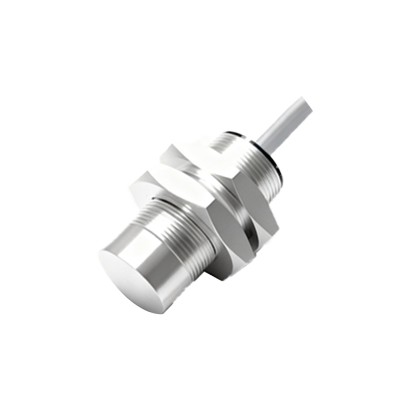
Step 2: Initial Bracket Mounting
Position the mounting bracket on the prepared surface. For adjustable brackets, like universal L-shaped or slide-style brackets, it is often advisable to initially set them to a mid-range position to allow for adjustment later. Use the provided hardware (bolts, nuts, washers) to loosely attach the bracket to the machine. Do not fully tighten at this stage. The goal is to have the bracket held in place but still movable for final alignment.

Step 3: Sensor Installation into the Bracket
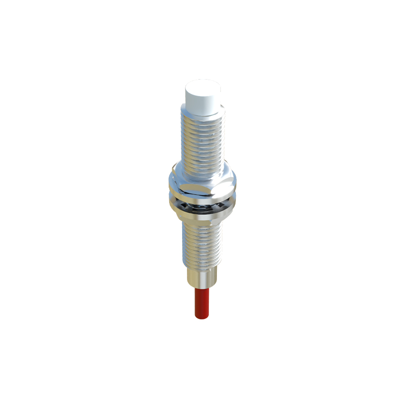
Insert the proximity sensor into its receptacle on the bracket. For threaded cylindrical sensors, carefully screw the sensor into the bracket's threaded hole by hand to avoid cross-threading. For sensors that clamp into place, follow the manufacturer's clamping procedure. Typically, you will hand-tighten the locking nut or clamping screw. Similar to the bracket itself, do not apply final torque yet. The sensor should be secure but still adjustable.
Step 4: Critical Alignment and Gap Setting
This is the most technically important phase. The sensor must be precisely aligned with its target. The target is the object it is meant to detect (e.g., a metal flag on a rotating shaft, a piston head). For standard inductive proximity sensors detecting metal, the sensing face must be parallel to the target's approach surface. Use a feeler gauge or the specified nominal sensing distance (Sn) as a reference. Adjust the bracket and sensor position to achieve the required gap. This gap is usually 50% to 80% of the sensor's rated nominal sensing distance (Sn) to account for mechanical tolerances, thermal expansion, and target wear. For example, for a sensor with an Sn of 5mm, set an initial operating gap of 2.5mm to 4mm. Ensure there is no risk of the target physically striking the sensor face during operation.
Step 5: Securing and Final Torquing
Once perfect alignment is achieved, begin the tightening sequence. First, gradually tighten the bracket's mounting bolts to the torque value specified in the manual. Overtightening can strip threads or warp the bracket, affecting alignment. After the bracket is fixed, proceed to tighten the sensor's locking mechanism (e.g., lock nut). For a threaded sensor with a lock nut, the standard practice is to hold the sensor body steady with one wrench while tightening the lock nut against the bracket with another. Apply the manufacturer's recommended torque. This prevents the sensor from rotating or vibrating loose during operation.
Step 6: Electrical Connection and Testing
With the sensor mechanically secured, you can proceed to make the electrical connections. Wire the sensor according to its type (PNP/NPN, NO/NC) and the schematic diagram. Use conduit or cable carriers to protect the cable from strain and damage. After all connections are made and double-checked, remove the LOTO devices and carefully energize the system. Conduct a functional test. Manually cycle the target object through its normal path. Observe the sensor's indicator LED (if equipped) and monitor the control system's input. Verify that the sensor triggers consistently and reliably at the expected position. If adjustment is needed, de-energize the system again before making any mechanical changes.
Step 7: Final Inspection and Documentation
Perform a final visual inspection to ensure all hardware is tight and the cable is not