In the realm of industrial automation, process control, and modern electronics, proximity sensing is a fundamental requirement for detecting the presence, absence, or position of an object without physical contact. Among the various technologies available, the Hall Effect proximity sensor stands out for its reliability, durability, and versatility. This article delves into the principles of operation, key characteristics, common applications, and practical considerations for selecting and implementing these essential components.
The core principle behind a Hall Effect sensor is the Hall Effect, discovered by Edwin Hall in 1879. It describes the generation of a voltage difference (the Hall voltage) across an electrical conductor when a magnetic field is applied perpendicular to the direction of electric current flow. A Hall Effect proximity sensor utilizes this phenomenon. It typically consists of a semiconductor-based Hall element, signal conditioning circuitry (including an amplifier), and a voltage regulator. When a permanent magnet or an electromagnet approaches the active face of the sensor, the magnetic flux density changes. This change causes a proportional variation in the Hall voltage generated by the element. The integrated circuitry processes this small signal, amplifying and converting it into a clean, usable digital (ON/OFF) or analog output signal that indicates the target's presence or distance.
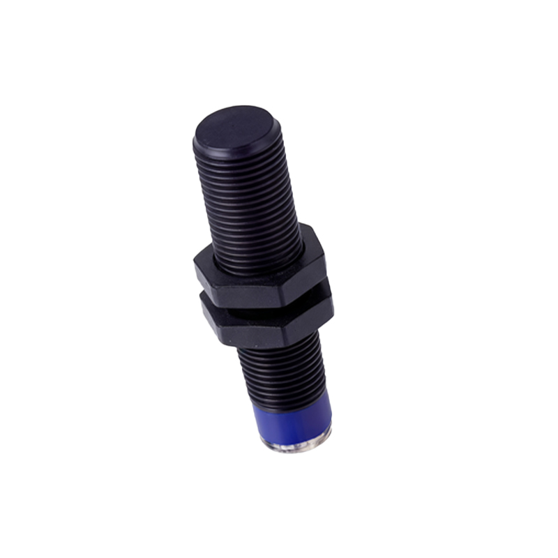
Several key features define Hall Effect sensors and contribute to their widespread adoption. First, they are true solid-state devices with no moving mechanical parts, leading to exceptionally long operational life, high reliability, and resistance to wear and tear. They can operate at very high switching frequencies, often in the range of several kilohertz, making them suitable for high-speed counting or speed detection applications. Unlike inductive sensors, Hall Effect sensors can detect both static (non-moving) and dynamic magnetic fields, allowing them to sense stationary magnets. They are generally immune to environmental factors such as dust, oil, moisture, and non-ferrous contaminants, as they respond solely to magnetic fields. Their output is consistent and precise, with minimal hysteresis.
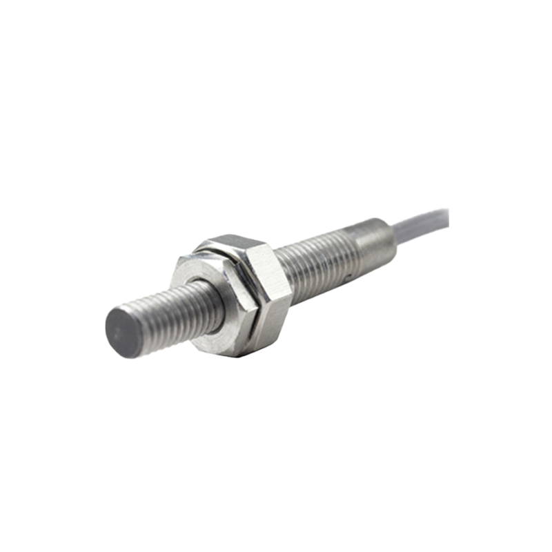
Hall Effect proximity sensors are categorized primarily by their output type. Digital (or switch) sensors provide a discrete ON or OFF signal when the magnetic flux exceeds a predefined threshold. These are further divided into unipolar (responding to one pole of a magnet) and bipolar (responding to both poles, often with a latching behavior). Analog (or linear) sensors produce a continuous output voltage or current that is proportional to the strength of the magnetic field, enabling them to measure distance or position with fine resolution.
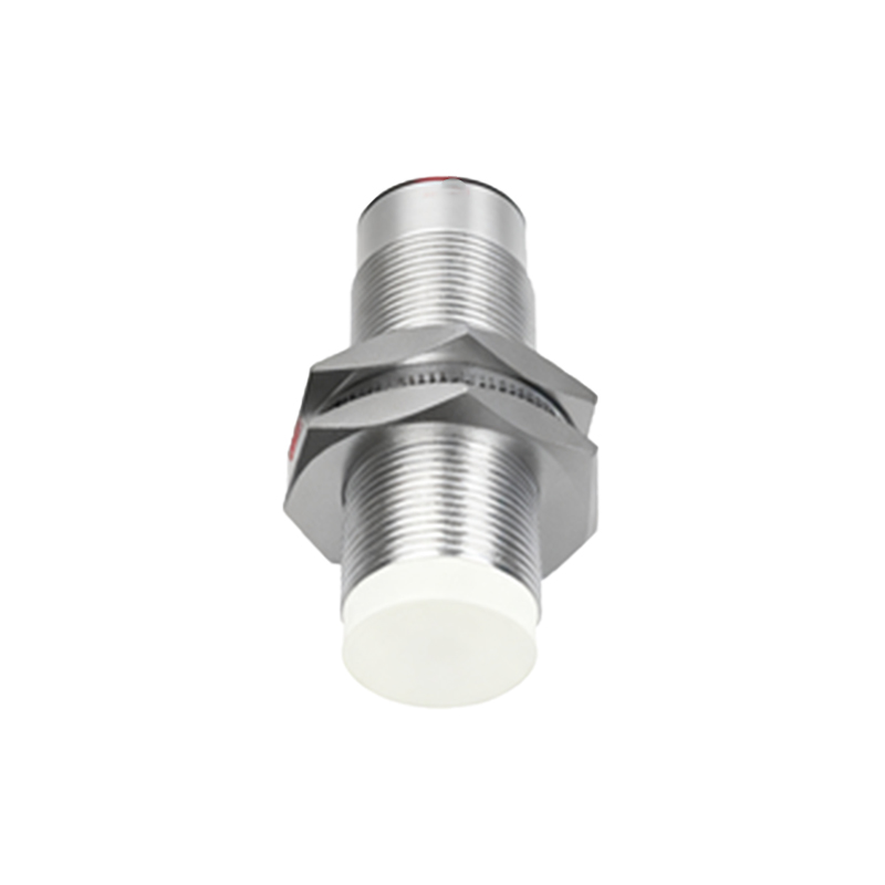
The applications for Hall Effect proximity sensors are vast and cross-industry. In the automotive sector, they are ubiquitous in anti-lock braking systems (ABS) for wheel speed sensing, in transmission systems for gear position detection, and in throttle and pedal position sensing. In industrial automation, they are used for end-of-travel detection on linear actuators, rotary speed sensing on motors and conveyors, and as non-contact limit switches in machinery. Consumer electronics employ miniature Hall sensors for lid or cover detection in laptops and smartphones, as well as in joysticks and control knobs. They are also critical in brushless DC (BLDC) motors for commutation, providing precise rotor position feedback.
Selecting the appropriate Hall Effect sensor for a specific application requires careful consideration of several parameters. The sensing distance, or operating point, must be specified, keeping in mind that it depends on the strength and size of the target magnet. The electrical output (NPN/PNP, NO/NC for digital; voltage/current range for analog) must be compatible with the control system (PLC, microcontroller). Supply voltage range, output current capability, and housing material (e.g., brass, stainless steel, PBT plastic) are chosen based on the electrical and environmental conditions, including temperature extremes, potential exposure to chemicals, and required ingress protection (IP) rating. The response time and switching frequency must meet the speed demands of the application. Finally, the physical form factor (tubular, rectangular, slot-type) is selected to fit the mechanical design constraints.
Installation and setup are generally straightforward but crucial for optimal performance. The sensor must be mounted securely to minimize vibration. The orientation between the sensor's active face and the target magnet is critical; the sensor is typically most sensitive along its central axis. For reliable switching, the magnetic field strength at the sensing point must exceed the sensor's operate point but drop below its release point to avoid erratic behavior. Shielding from stray magnetic fields from nearby motors or heavy currents may be necessary in some installations.
In summary, Hall Effect proximity sensors are indispensable tools in modern engineering, offering a robust, contactless solution for position and speed detection. Their operation based on a fundamental physical principle translates into predictable and stable performance across demanding environments. By understanding their working principle, key specifications, and application nuances, engineers and technicians can effectively leverage these sensors to enhance the intelligence, safety, and efficiency of countless systems, from factory floors to everyday devices