In the dynamic landscape of industrial automation and safety systems, proximity sensors are indispensable components. Among the various designs, the hourglass proximity sensor, named for its distinctive tapered or dual-cone shape, offers unique advantages in specific applications. This guide provides a comprehensive, practical overview of how to effectively integrate and utilize an hourglass proximity sensor in your electrical and control systems.
Understanding the Hourglass Design Principle
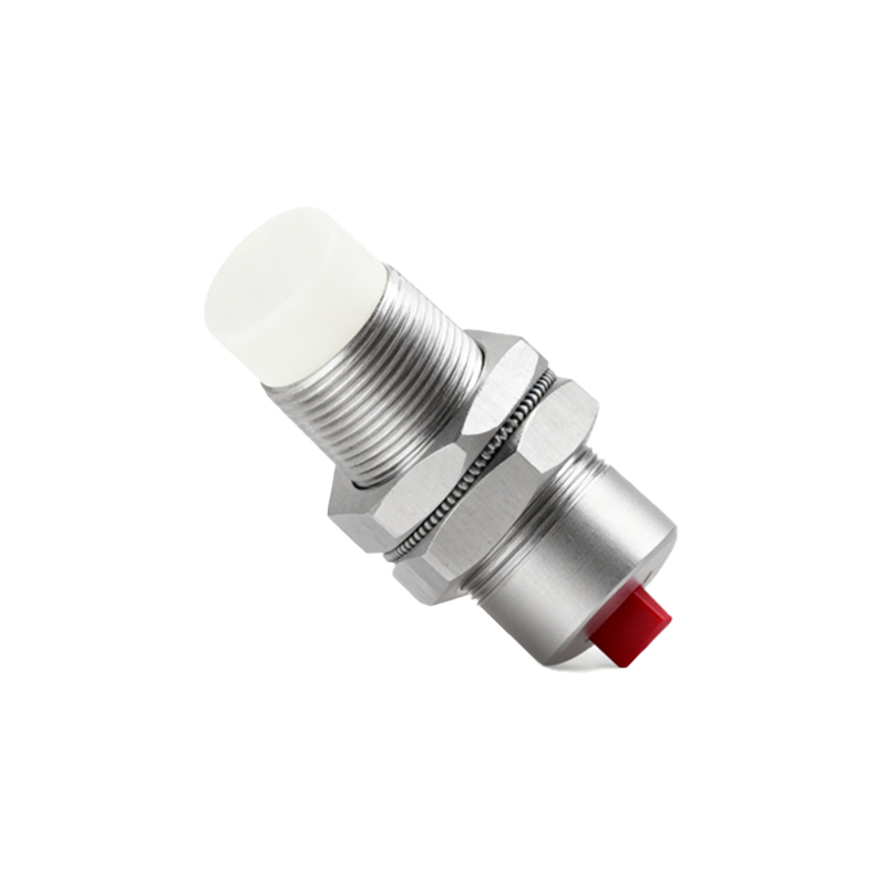
Unlike standard cylindrical sensors, the hourglass sensor features a narrowed central section. This design is not merely aesthetic; it fundamentally alters the sensor's electromagnetic or ultrasonic field pattern. The constricted middle creates a more focused and defined sensing field at the center, while the flared ends can help in mounting or housing the emitter and receiver elements (in opposed-mode sensors) or in shaping the field for a particular detection profile. This shape is particularly common in certain photoelectric and ultrasonic proximity sensors where beam concentration or specific angular detection is required. The key benefit is the ability to detect objects within a very precise zone, minimizing false triggers from the peripheral environment—a common challenge in cluttered industrial settings.

Step-by-Step Application Guide
1. Selection and Specification: The first step is always proper selection. Identify the core requirement: sensing range, target material (metal, plastic, liquid), output type (PNP/NPN analog, digital, IO-Link), and environmental factors (IP rating, temperature, exposure to chemicals). The hourglass shape often correlates with a sensor designed for a restricted sensing zone or for through-beam applications where alignment is critical. Consult the manufacturer's datasheet for the exact field diagram; do not assume it behaves like a standard sensor.
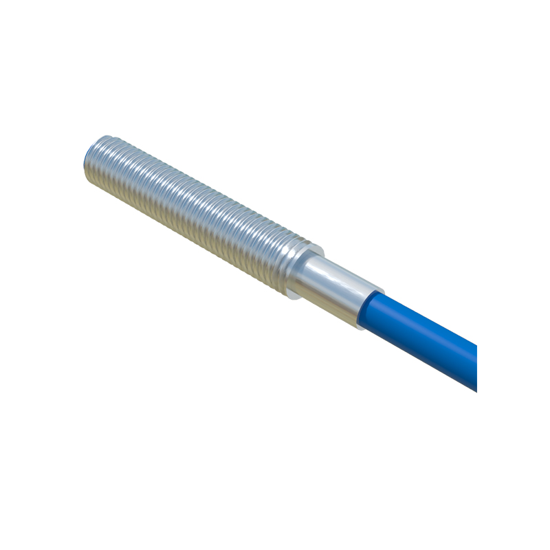
2. Mechanical Installation: Precision mounting is paramount. Utilize the sensor's built-in brackets or threaded sections (commonly found at the flared ends). Ensure the sensor is securely fastened to prevent vibration-induced misalignment. The most critical aspect is aligning the sensitive "waist" of the hourglass with the target's path. For opposed-mode (through-beam) types, the emitter and receiver must be perfectly aligned across the gap. The hourglass design often aids in initial coarse alignment via visual guides. Use laser alignment tools if available for the highest precision, especially for longer ranges.
3. Electrical Wiring and Connection: Follow the standard electrical safety protocol: Lock Out, Tag Out (LOTO). Connect the sensor to the power supply as per its voltage rating (typically 10-30V DC for solid-state models). Connect the output wire(s) to your PLC (Programmable Logic Controller), relay, or other control unit. Pay close attention to the wiring diagram: Brown wire is usually for DC+ (24V), Blue for DC- (0V), and Black (or another color) for the switched output signal. Ensure proper grounding and consider using shielded cables in electrically noisy environments to prevent signal interference.
4. Configuration and Calibration: Many modern hourglass proximity sensors, especially analog or smart models, feature configurability. Use teach-in buttons, potentiometers, or software via IO-Link to set parameters like sensing range, output delay (on/off delay), and hysteresis. For simple digital sensors, the only adjustment might be a sensitivity potentiometer. Calibrate the sensor with the actual target object present. Move the target through the desired detection point and adjust the sensitivity so the output switches reliably at the exact position required, without triggering on background objects.
5. Testing and Validation: Before integrating into the full system cycle, conduct rigorous testing. Use the actual target material and simulate the full range of operating speeds and environmental conditions (e.g., temperature cycles, dust exposure). Monitor the output on an oscilloscope or PLC input monitor to check for signal integrity and the absence of chatter. Implement a validation routine in your control logic, such as a heartbeat check or a reasonableness test on sensing timing.
Common Industrial Use Cases
Object Positioning on Conveyors: Precisely detecting the leading edge of a package or component for triggering a pusher, printer, or robotic picker.
Web Break Detection: In material handling (paper, film, textiles), the focused beam can detect a very thin thread or the presence/absence of a material running at high speed.
Fill Level Control in Narrow Necks: The focused sensing zone is ideal for detecting the presence of liquid or granular material inside the narrow neck of a bottle or silo, avoiding false signals from the container walls.
Security and Safety Light Curtains: Some light curtain emitters/receivers use an hourglass lens design to create a precise, columnated beam array for intrusion detection in hazardous areas.
Small Part Assembly Verification: Ensuring a tiny screw, spring, or electronic component is present in a specific location