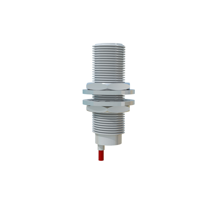
In industrial automation and control systems, 24V proximity sensors are widely used for non-contact detection of metallic objects. Proper grounding is critical to ensure reliable operation, minimize electrical noise, and prevent false triggering or sensor failure. This article discusses the grounding results of 24V proximity sensors, common issues, and recommended practices based on engineering experience.
When a 24V proximity sensor is correctly grounded, it typically exhibits stable performance with consistent sensing ranges and minimal interference. The grounding path provides a low-impedance return for leakage currents and noise, shielding the sensor from electromagnetic interference (EMI) generated by nearby motors, drives, or high-frequency equipment. A well-grounded sensor also reduces the risk of voltage spikes damaging the internal circuitry, thereby extending its operational lifespan. In many installations, the sensor's metal housing or mounting bracket is connected to the system ground, while the DC common (0V) of the power supply is also grounded at a single point to avoid ground loops.
However, improper grounding can lead to several adverse results. One common issue is ground loops, where multiple ground points create circulating currents that introduce noise into the sensor signal. This may cause erratic behavior, such as intermittent detection or false positives. Another problem is floating grounds, where the sensor's ground reference is not properly established, leading to unstable output signals or complete failure to detect targets. In some cases, inadequate grounding can result in electrical shocks or safety hazards, especially in wet or corrosive environments. Additionally, sensors may experience reduced sensing distance or increased susceptibility to temperature variations when grounding is insufficient.
To achieve optimal grounding results, follow these best practices: First, use a dedicated ground wire for the sensor, connecting it directly to a solid earth ground point rather than daisy-chaining grounds with other devices. The wire should be as short and thick as possible to minimize impedance. Second, ensure the power supply's DC negative (0V) is grounded at one point only, typically at the power supply unit, to prevent ground loops. Third, isolate sensor cables from high-voltage or high-current lines by routing them separately or using shielded cables with the shield grounded at one end. Fourth, in environments with high EMI, consider using ferrite cores or filters on the sensor cables. Finally, regularly inspect ground connections for corrosion or looseness, as these can degrade performance over time.
Testing grounding effectiveness can be done using a multimeter to measure resistance between the sensor ground and earth ground (ideally below 1 ohm) and checking for AC voltage noise on the signal line (should be minimal). Oscilloscopes can also help visualize noise levels. Remember that different sensor types (e.g., inductive, capacitive) or output configurations (PNP vs. NPN) may have specific grounding requirements, so always refer to the manufacturer's guidelines.
In summary, proper grounding of 24V proximity sensors is essential for reliable industrial automation. By avoiding common pitfalls and adhering to established practices, engineers can ensure accurate detection, reduced downtime, and enhanced system safety.