In modern industrial automation and precision measurement systems, the integration of laser sensors with display screens is a fundamental task for monitoring and visualizing real-time data. This process, while straightforward in concept, requires careful attention to electrical compatibility, communication protocols, and software configuration to ensure accurate and reliable operation. This guide provides a step-by-step approach for engineers to successfully interface a laser sensor with a display unit, covering essential hardware connections, signal processing, and common troubleshooting techniques.
The first step involves selecting the appropriate laser sensor and display screen based on the application requirements. Laser sensors are available in various types, including time-of-flight, triangulation, and confocal sensors, each suited for specific measurement ranges, resolutions, and environmental conditions. Similarly, display screens can range from simple LED panels to sophisticated touchscreen HMIs (Human-Machine Interfaces) or industrial PCs. Key specifications to consider include the sensor's output signal type (analog voltage/current, digital pulses, or serial data) and the display's input compatibility. Most industrial displays support standard analog inputs (0-10V or 4-20mA) or digital communication protocols like RS-232, RS-485, Modbus, or Ethernet/IP.
Once the components are selected, the physical connection must be established. Begin by powering down all equipment to prevent electrical damage. Connect the laser sensor to a stable power supply, typically 12-24V DC, as per the manufacturer's datasheet. The output signal cable from the sensor should then be routed to the display's input terminals. For analog sensors, connect the signal wire to the display's analog input channel, ensuring proper grounding to minimize noise interference. Shielded cables are highly recommended for long-distance runs or in electrically noisy environments. For digital sensors using serial communication, connect the TX (transmit) and RX (receive) pins accordingly, often requiring a null-modem cable or adapter. Always refer to the pinout diagrams in the technical manuals.
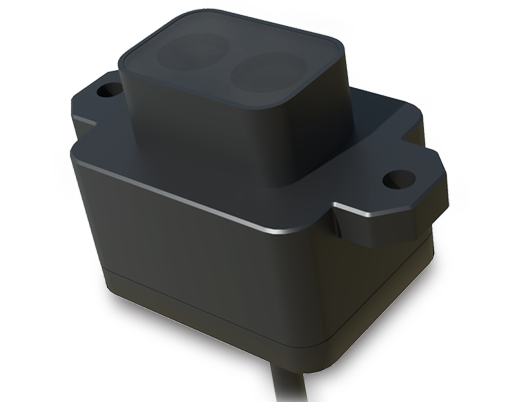
After hardware wiring, configure the display screen to interpret the incoming sensor data. Access the display's configuration menu—usually through onboard buttons or software—to set parameters such as input type, scaling, and engineering units. For an analog input, define the input range (e.g., 0-10V) and map it to the corresponding measurement range of the laser sensor (e.g., 0-500mm). This linear scaling converts the raw voltage signal into a meaningful distance value. For digital protocols, set the correct baud rate, data bits, parity, and stop bits to match the sensor's communication settings. Many modern displays with protocol support can automatically parse data strings; otherwise, manual parsing may be needed to extract the relevant measurement value.
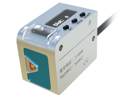
Software integration is crucial for advanced functionality. If using an HMI or SCADA system, create a graphical representation of the sensor data, such as numeric displays, trend graphs, or bar indicators. Implement alarms to trigger when values exceed predefined thresholds, enhancing process control. Ensure the update rate of the display aligns with the sensor's sampling rate to avoid data lag. For networked systems, verify IP addresses and subnet masks if using Ethernet-based communication.
Testing and validation are essential before deployment. Power on the system and observe the display for stable readings. Perform a calibration check by placing known reference objects within the sensor's range and comparing the displayed values. If discrepancies occur, re-verify connections, scaling parameters, and grounding. Common issues include signal drift due to power fluctuations, communication errors from incorrect baud rates, or electromagnetic interference. Use an oscilloscope or multimeter to diagnose analog signal integrity, and check protocol monitors for digital data frames.
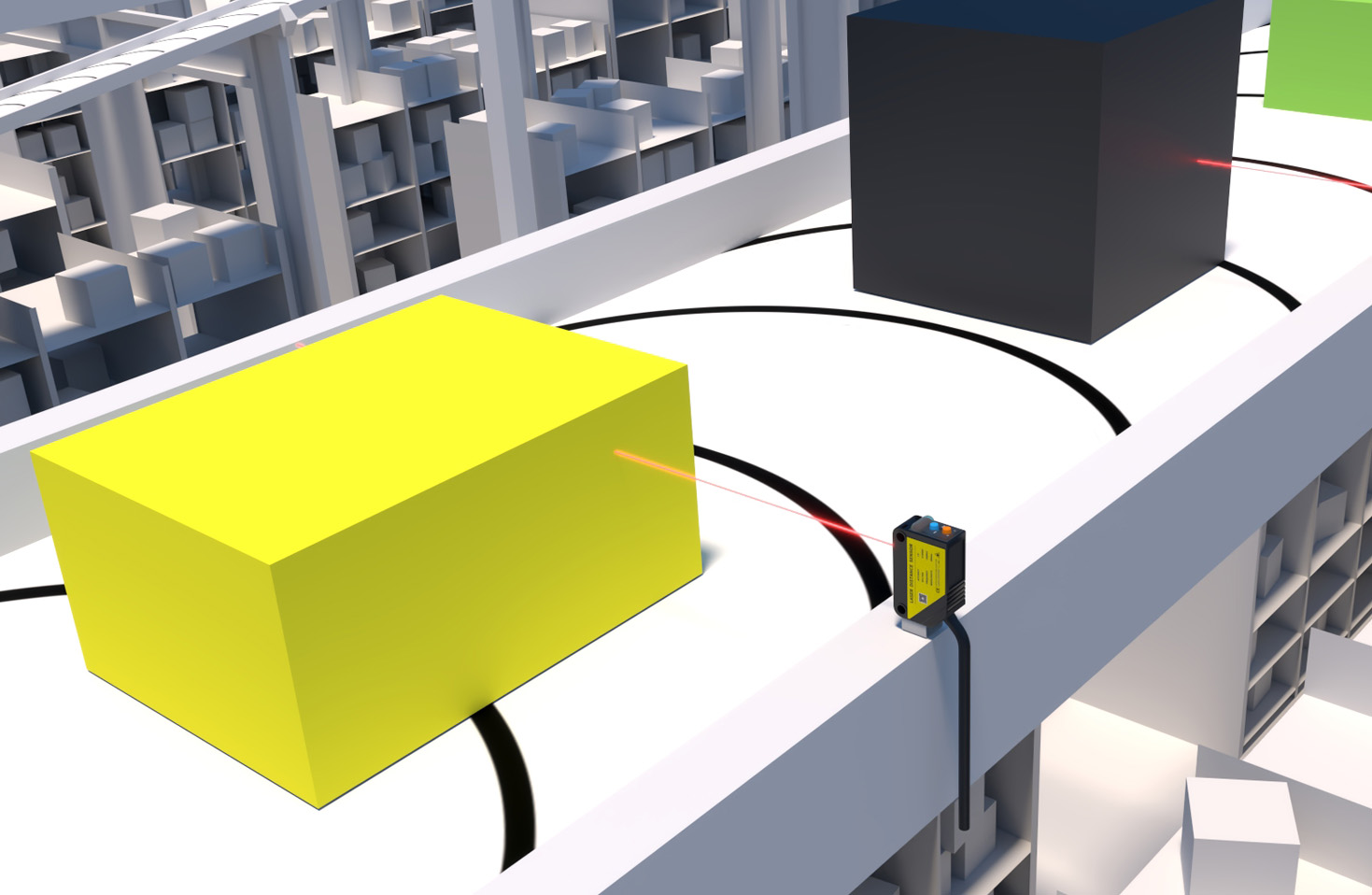
In summary, connecting a laser sensor to a display screen is a systematic process that blends electrical engineering with software configuration. By meticulously addressing hardware compatibility, signal integrity, and parameter settings, engineers can achieve seamless integration for real-time monitoring. This capability is vital in applications like assembly line inspection, robotic guidance, and dimensional analysis, where precise visual feedback drives operational efficiency and quality assurance. Regular maintenance, including cable inspections and firmware updates, further ensures long-term reliability in demanding industrial environments.