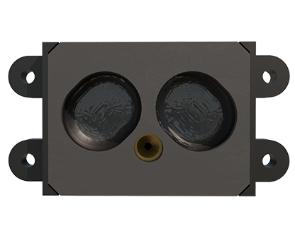
Multi-point laser sensors have become indispensable components in modern industrial automation, offering high-precision measurement, detection, and positioning capabilities across various applications such as assembly verification, object profiling, and dimensional inspection. Proper wiring is fundamental to ensuring these sensors operate reliably within complex control systems. This guide details the essential principles and procedures for wiring multi-point laser sensors, emphasizing safety, signal integrity, and integration with industrial networks.
The first step involves meticulous planning before any physical connection. Always consult the sensor's datasheet from the manufacturer. Key specifications to verify include the supply voltage (commonly 12-24 VDC), current consumption, output type (digital NPN/PNP, analog voltage/current, or serial communication like IO-Link), and the function of each pin on the connector. Most multi-point sensors feature a multi-pin M12 or M8 circular connector, standardized for industrial environments. A typical wiring scheme includes pins for power supply (V+ and V- or 0V), one or more digital outputs for switching states, and sometimes a dedicated pin for diagnostic feedback or teach-in functions.

For power wiring, use shielded, twisted-pair cables to minimize electromagnetic interference (EMI). Connect the positive supply wire (e.g., 24V) to the designated V+ pin and the negative/0V wire to the COM or V- pin. Ensure the power source is stable and within the sensor's rated range; voltage fluctuations can cause erratic behavior or damage. Implement appropriate circuit protection, such as a slow-blow fuse or a circuit breaker, in the supply line. The grounding (earth) connection is critical. Connect the cable shield to a solid earth ground point at the control cabinet, typically via a cable gland with an integrated shield clamp. Avoid grounding the shield at both ends in most cases to prevent ground loops.
Output wiring depends on the sensor's configuration. For digital switching outputs (NPN sinking or PNP sourcing), connect the load (e.g., a PLC input module, relay, or indicator) correctly. For an NPN output, the load is connected between the sensor's output pin and the positive supply; the sensor sinks current to 0V when active. For a PNP output, the load is connected between the output pin and 0V; the sensor sources current from V+. Always observe the maximum load current specified. For analog outputs (e.g., 0-10V or 4-20mA), use a dedicated pair of wires to the analog input card, ensuring the cable run is away from high-voltage power lines to avoid noise coupling.
Multi-point sensors often feature configurable outputs for different measurement points or zones. Wiring for these may involve separate output pins for each point or a multiplexed signal over a single line using a protocol like IO-Link. IO-Link wiring simplifies connectivity by using a standard 3-wire M12 cable (V+, 0V, and signal) while enabling bidirectional digital communication for parameter setting, diagnostics, and advanced data transmission. When daisy-chaining multiple sensors on a network like PROFINET or EtherNet/IP, follow the network topology guidelines and use certified industrial Ethernet cables with proper connectors.
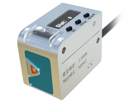
After all connections are made, perform a systematic check. Visually inspect for secure connections, correct pin assignments, and no stray wires. Use a multimeter to verify supply voltage at the sensor connector with no power applied to the load. Power up the system and observe the sensor's indicator LEDs (Power, Output status). Test the sensor's function by introducing a target object; verify the output switches or analog signal changes as expected at the controller. Consult the manual for any teach-in or calibration procedures that might require a specific wiring sequence or button press after installation.
Common pitfalls to avoid include using incorrect wire gauge (too thin can cause voltage drop), neglecting cable strain relief, running sensor cables in parallel with motor power cables, and forgetting to enable the correct input type on the PLC (e.g., sourcing vs. sinking). Proper wiring, combined with adherence to EMC guidelines and regular maintenance, ensures long-term, stable operation of multi-point laser sensor systems, maximizing their precision and contributing to overall system uptime and productivity.