In industrial automation systems, proximity sensors play a critical role in non-contact detection of metallic and non-metallic objects. The performance and reliability of these sensors are intrinsically linked to the quality, design, and installation of their connecting cables. Often overlooked as a simple accessory, the cable is a vital component that ensures signal integrity, protects against environmental hazards, and guarantees long-term operational stability. This article delves into the key engineering considerations for selecting and deploying proximity sensor cables in demanding industrial environments.
The primary function of a proximity sensor cable is to transmit the sensor's switching signal or analog output to the control system, typically a PLC (Programmable Logic Controller). Therefore, electrical characteristics are paramount. Cable construction begins with the conductor. Stranded copper conductors are preferred over solid core for their superior flexibility and resistance to breakage from repeated bending or vibration, common in machinery. The gauge (AWG) must be sized appropriately for the current carrying capacity and to minimize voltage drop over the required run length, especially for sensors with longer cable-as-antenna designs or those requiring power supply through the same cable.
Insulation and jacketing materials are selected based on the operating environment. Common insulation materials like PVC (Polyvinyl Chloride) offer good general-purpose protection. However, for areas with exposure to oils, coolants, or chemicals, cables with PUR (Polyurethane) or TPE (Thermoplastic Elastomer) jackets are essential. These materials provide excellent resistance to degradation, ensuring the cable does not become brittle or crack. For high-temperature applications near ovens or welding stations, silicone rubber or PTFE (Teflon) insulated cables can withstand continuous exposure to extreme heat without compromising performance.
Shielding is a non-negotiable feature for most industrial proximity sensor applications. Electromagnetic interference (EMI) from motors, variable frequency drives (VFDs), and welding equipment can induce noise on the signal lines, leading to false triggering or signal loss. A braided copper shield, often combined with an aluminum foil layer, provides effective protection against both capacitive and inductive coupling. This shield must be properly terminated and grounded at the control panel end to create a path for interference to drain to earth, preventing it from affecting the sensitive sensor electronics.
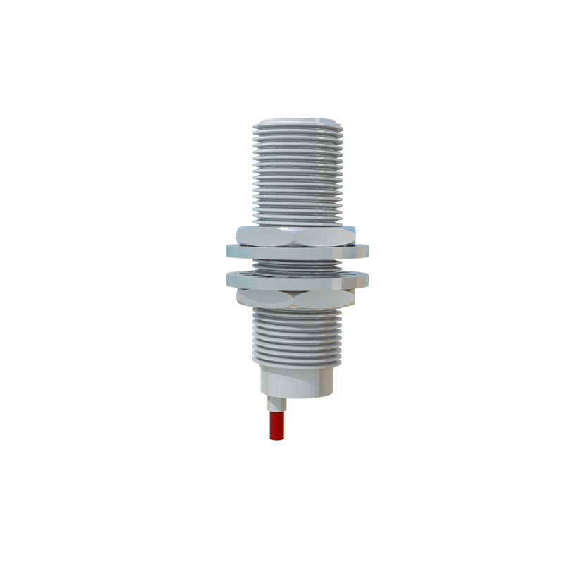
The mechanical robustness of the cable is tested daily in factories. Key attributes include crush resistance, tensile strength, and flexibility. Many industrial sensor cables feature an integrated strain relief at the sensor connection point. This molded section absorbs mechanical stress, preventing pull forces from being transferred directly to the solder joints or terminations inside the sensor housing. For applications with continuous flexing, such as on cable carriers or robotic arms, specially designed "high-flex" cables with finely stranded conductors and optimized jacket compounds are mandatory to achieve millions of flex cycles without failure.
Connector choice is equally critical. Many proximity sensors feature quick-disconnect (QD) styles like M8 or M12 connectors, which are standardized under IEC 61076-2. These circular connectors provide IP67 or IP68 ratings for dust and water ingress protection when mated. It is crucial to specify the correct pin configuration (e.g., 3-pin for DC switching, 4-pin for analog or IO-Link sensors, 5-pin for certain diagnostic functions) and coding (A-coded for sensors/actuators, B-coded for fieldbus) to ensure compatibility. For hard-wired sensors, the cable entry is typically sealed with a gland to maintain the sensor's IP rating.
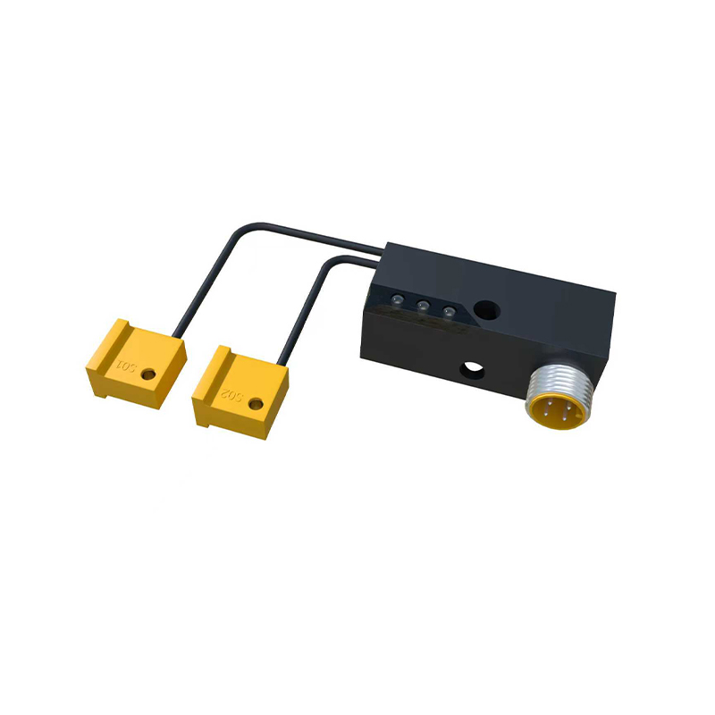
Installation best practices are the final step to ensuring reliability. Cables should be routed away from high-power lines and sources of EMI whenever possible. If crossing power cables is unavoidable, it should be done at a 90-degree angle to minimize inductive coupling. Secure cabling with clamps or cable ties at regular intervals to avoid dangling loops, but avoid over-tightening, which can deform the cable and damage internal conductors. Always leave a service loop near the sensor and the control panel to allow for future maintenance or repositioning without tension on the connections. Finally, adhere to all local and national electrical codes for industrial wiring.
In conclusion, specifying the correct proximity sensor cable is an engineering decision that impacts system uptime, maintenance costs, and safety. By carefully evaluating electrical requirements, environmental conditions, mechanical stresses, and connector interfaces, engineers can select a cable solution that ensures the proximity sensor performs as intended throughout its service life. A robust cable, installed with foresight, is the best insurance against costly downtime and unreliable operation in automated production systems.