In industrial automation, laser line tracking sensors are critical components for precision guidance, alignment, and measurement. Proper calibration and troubleshooting are essential to ensure these sensors deliver reliable, accurate data. This guide outlines a systematic approach to debugging laser tracking sensors, combining theoretical principles with hands-on techniques.
The core of a laser line sensor is its ability to project a visible or infrared laser line onto a target surface and capture the reflected pattern with a CMOS or CCD camera. Displacement or profile changes alter the line's shape in the camera's field of view. The onboard processor analyzes this deformation to calculate measurements like height, width, or position. Therefore, any debugging process must consider three interconnected elements: the optical path (laser and lens), the imaging system (camera and processor), and the target surface itself.
A standard debugging procedure begins with a visual and physical inspection. Ensure the sensor is securely mounted, free from vibration, and that its lens is clean and unobstructed. Check all electrical connections for the power supply and communication cables (e.g., Ethernet, IO-Link, or discrete I/O). Even a slightly loose connector can cause intermittent failures.
Next, verify the installation geometry. The sensor's optimal working distance and field of view are specified in its datasheet. Use a calibration gauge or a known-reference object to confirm the sensor is mounted at the correct distance and angle relative to the target. Misalignment is a leading cause of systematic error. For line tracking, the laser line should be projected perpendicular to the primary direction of movement for most applications.
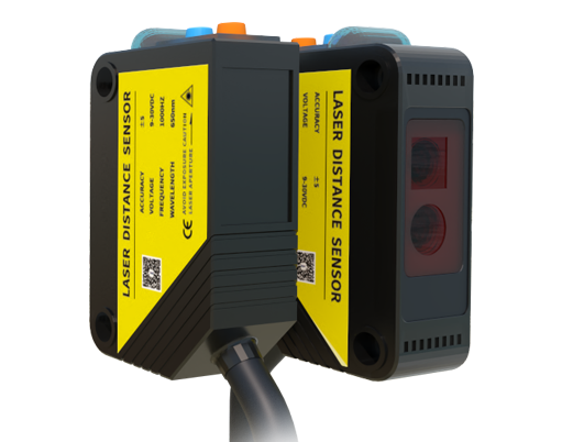
Power on the sensor and connect to its configuration software, which is typically provided by the manufacturer. The first software-based step is often a "Reference" or "Teach" procedure. This involves presenting the sensor with a known-good target or a "zero" condition (like a flat, standard surface). The sensor captures this as its baseline profile. All subsequent measurements are deviations from this reference. Skipping or incorrectly performing this step will compromise all readings.

After establishing a reference, test the sensor with a sample target. Observe the raw camera image or profile graph in the software. A clear, sharp laser line with high contrast against the background is ideal. Common issues visible here include:
1. Faint or Broken Laser Line: Could indicate low laser power (check settings), dirty optics, excessive ambient light, or a target surface that is too dark, shiny, or transparent.
2. Saturated or Blurred Line: Often caused by the sensor being too close to a highly reflective surface, requiring a gain adjustment or the use of a filter.
3. Noisy/Unstable Profile: Typically results from electrical interference, vibration, or a speckled target surface. Enabling software filtering (averaging) can help.
For environmental light interference, which is a frequent challenge, solutions include: adjusting the sensor's exposure time, using a narrower optical bandpass filter matched to the laser's wavelength, installing physical shrouds around the sensor and target area, or utilizing sensors with modulated laser light that can differentiate its own signal from ambient noise.
Communication and output verification is the next critical phase. Configure the desired output parameters (e.g., switching threshold, analog output scaling, or serial data format). Use a simple test—like passing an object of a known height under the sensor—and monitor the output. Measure the analog voltage with a multimeter or observe the digital output states. Ensure the output responds correctly and within the expected response time. If using network protocols, verify data packets are being sent and received correctly using a protocol analyzer or the host PLC's diagnostics.
When troubleshooting persistent errors, adopt a methodical isolation approach. If readings are erratic, try swapping the sensor with a known-working unit on the same setup. If the problem follows the sensor, the issue is likely internal (e.g., a failing laser diode or camera). If the problem remains at the location, the issue is environmental (e.g., lighting, target material, or electrical noise). Similarly, test with different target materials to rule out surface property issues.
Advanced calibration might involve creating a height map or correcting for optical distortion across the entire field of view, especially for large-area sensors. Some software allows for multi-point linearization, where you input known measurements at several points, and the software creates a correction curve.
Finally, document all settings, reference values, and environmental conditions. This log is invaluable for future maintenance, replication of the setup on other machines, or diagnosing drift over time. Regular preventive maintenance, including lens cleaning and verification checks against a master gauge, will minimize unplanned downtime.
Remember, a laser sensor is part of a system. Always consider the interplay between the sensor's performance, the mechanical stability of the installation, the properties of the target, and the electrical environment. Successful debugging is not just about fixing an error but optimizing the entire measurement chain for long-term, stable operation.