Metal proximity sensors are indispensable components in modern industrial automation, widely used for object detection, positioning, and counting in machinery, assembly lines, and robotic systems. Their non-contact operation offers significant advantages in harsh environments. However, like all electronic devices, they are susceptible to various faults that can disrupt production. Understanding these common failures and their remedies is crucial for maintaining operational efficiency and minimizing downtime.
One of the most frequent issues is False Triggering or No Triggering. This manifests as the sensor activating without a target present or failing to detect a valid target. The root causes are often environmental. Electrical noise from nearby motors, variable frequency drives (VFDs), or welding equipment can induce spurious signals in the sensor or its wiring. To resolve this, ensure proper shielding of the sensor cable. Using twisted-pair, shielded cables and grounding the shield at only one end (typically the controller end) is essential. Increasing the distance between the sensor and noise sources or installing ferrite cores on the cable near the sensor can also be effective. Another cause is the presence of non-target metals in the sensing field. Always verify the installation environment and adjust the sensing distance, ensuring the target metal type and size are within the sensor's specified range.
Reduced Sensing Distance is another common problem. Over time, a sensor may only detect targets at a distance shorter than its rated specification. The primary culprit is often contamination. Accumulation of metallic dust, chips, or non-metallic debris like oil, grease, or dirt on the sensor's active face can dampen the electromagnetic field. Regular cleaning of the sensor face with a soft, non-abrasive cloth and appropriate solvents is necessary. Physical damage to the sensing face or internal components from impact can also cause this issue, potentially requiring sensor replacement. Additionally, check for power supply voltage fluctuations. Operating below the minimum rated voltage can significantly reduce performance.
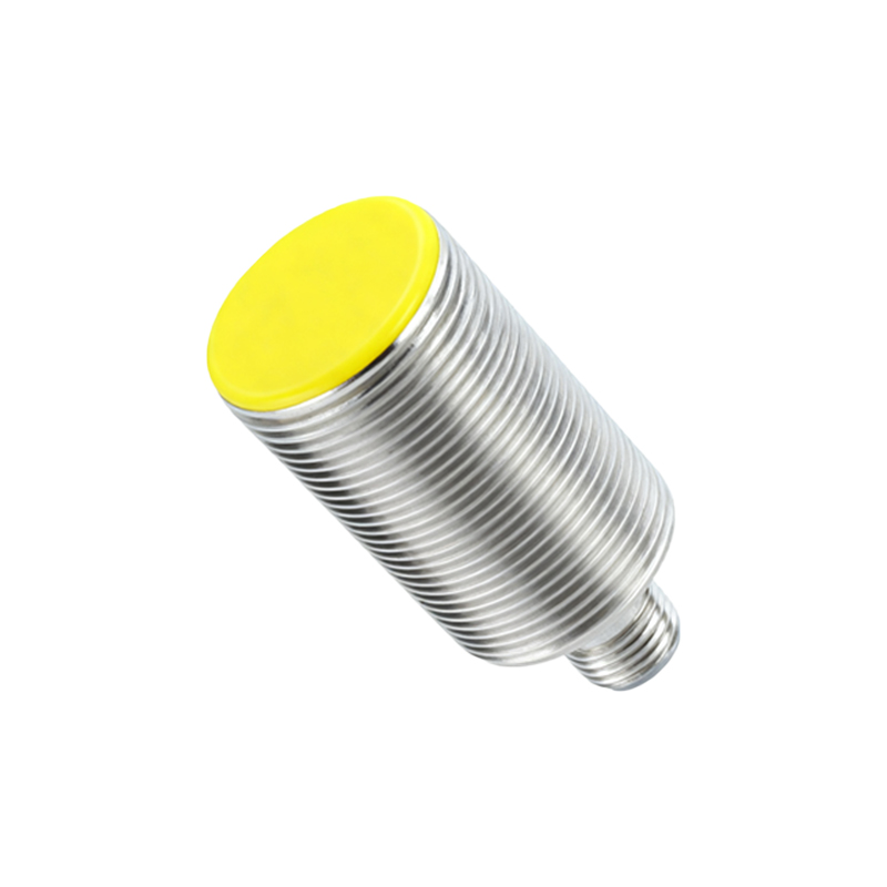
Intermittent Operation poses a particularly challenging diagnostic problem. The sensor works sporadically, leading to unpredictable system behavior. This is frequently related to wiring and connections. Loose terminal screws, corroded contacts, or damaged cable cores from constant flexing or pinch points can create intermittent connections. Thoroughly inspect the entire wiring path from the sensor to the controller. Tighten all connections and check for broken wires. Vibration in the mounting location can also loosen connections or internally damage the sensor. Ensure the sensor is securely mounted using appropriate brackets, and consider using vibration-dampening mounts if necessary.
Sensor Failure (No Output) occurs when the sensor shows no response, indicated often by a non-illuminated status LED. First, perform basic checks: confirm the power supply is present and within the specified voltage range (e.g., 10-30V DC). Verify the wiring is correct according to the datasheet (brown wire to +V, blue wire to 0V, black wire to load). A simple test is to swap the sensor with a known-good unit from a similar application. If the new sensor works, the original is likely faulty. Internal failure can result from prolonged exposure to extreme conditions beyond its specifications, such as excessive temperature, humidity, or direct washdown with high-pressure chemicals if not rated for such an environment.
Incorrect Sensing Due to Target Characteristics is an application error rather than a sensor fault, but it frequently leads to perceived failure. Not all metals are detected equally. Factors like target size, shape, and material (e.g., steel, aluminum, stainless steel, brass) greatly affect the effective sensing distance. A sensor calibrated for mild steel will have a reduced range for aluminum or stainless steel. Always consult the sensor's reduction factor chart. The target must also be large enough to intersect the sensor's electromagnetic field adequately. For small fasteners or thin sheets, selecting a sensor with a higher frequency or a specialized design may be required.
Preventive Maintenance and Best Practices can avert many common faults. Implement a regular schedule for visual inspection and cleaning. During installation, adhere strictly to the manufacturer's guidelines regarding mounting (flush or non-flush), mutual interference distances between multiple sensors, and environmental ratings (IP67, IP69K, etc.). Use sensors with built-in diagnostics or output status indicators whenever possible. For critical applications, consider installing redundant sensors in a voting logic configuration to enhance reliability.
In conclusion, systematic troubleshooting of metal proximity sensors starts with the simplest checks: power, connections, and environment. By methodically eliminating common causes like noise, contamination, and wiring faults, maintenance personnel can quickly restore functionality or identify a genuinely faulty unit for replacement. A deep understanding of both the sensor's principles and its specific application context is the key to ensuring long-term, reliable operation in any industrial setting.