Proximity switch sensors are widely used in industrial automation for detecting the presence or absence of objects without physical contact. Integrating these sensors with microcontrollers enables precise control and data acquisition in various applications, such as assembly lines, robotics, and safety systems. This guide provides a detailed overview of wiring diagrams for connecting proximity switch sensors to microcontrollers, focusing on common types like inductive, capacitive, and photoelectric sensors.
First, understand the basic components of a proximity switch sensor. Typically, it consists of three wires: power supply (Vcc), ground (GND), and output signal (OUT). The power supply voltage varies depending on the sensor model, often ranging from 5V to 24V DC. The output signal can be either digital (high/low) or analog, with digital outputs being more common for microcontroller interfacing. For example, an NPN-type sensor sinks current to ground when activated, while a PNP-type sources current to the output.
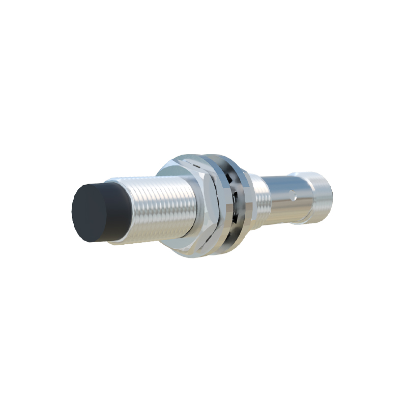
To connect a proximity sensor to a microcontroller, start by identifying the sensor's specifications from its datasheet. Ensure compatibility between the sensor's voltage levels and the microcontroller's input pins. Most microcontrollers, such as Arduino or STM32, operate at 5V or 3.3V logic levels. If the sensor outputs a higher voltage, use a voltage divider or level shifter to prevent damage. For digital sensors, wire the Vcc pin to the microcontroller's power supply (e.g., 5V pin), the GND pin to the microcontroller's ground, and the OUT pin to a digital input pin on the microcontroller. Add a pull-up or pull-down resistor if needed to stabilize the signal.
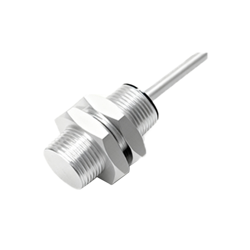
For analog proximity sensors, the output is a continuous voltage proportional to the detected distance. Connect the output to an analog input pin on the microcontroller, such as ADC0 on an Arduino. Calibrate the sensor by reading the analog values and mapping them to distance measurements in the code. Always include decoupling capacitors near the sensor's power pins to filter noise, especially in industrial environments with electrical interference.
In complex setups, multiple sensors can be connected to a single microcontroller using multiplexers or by utilizing multiple I/O pins. Ensure proper isolation for sensors operating in high-voltage circuits to protect the microcontroller. For instance, use optocouplers or relays to separate the sensor's power domain from the microcontroller's logic domain.
Programming the microcontroller involves reading the sensor's output and triggering actions based on the input. For digital sensors, use functions like digitalRead() in Arduino to detect state changes. For analog sensors, use analogRead() and implement threshold logic in the code. Consider adding debouncing routines for digital sensors to avoid false triggers from noise.
Safety precautions are crucial when wiring proximity sensors. Always disconnect power before making connections. Use shielded cables for long runs to reduce electromagnetic interference. Test the circuit with a multimeter to verify voltage levels before powering the microcontroller. In industrial settings, follow standards like IEC 61131 for wiring practices.
In summary, wiring proximity switch sensors to microcontrollers requires attention to voltage compatibility, signal types, and noise reduction. By following these guidelines, engineers can build reliable systems for automation projects. For further details, refer to sensor datasheets and microcontroller documentation.