In the intricate world of industrial automation, the reliability and precision of sensing components are paramount. Among the diverse array of sensors, the inductive proximity sensor stands as a cornerstone for non-contact detection of metallic objects. The Proximity Sensor W12 represents a specific, widely utilized model within this category, known for its robust performance in demanding environments. This article delves into the technical specifications, operational principles, application scenarios, and selection criteria for the W12, providing a detailed guide for engineers and maintenance professionals.
The Proximity Sensor W12 is typically a cylindrical, shielded (flush-mountable) inductive sensor. Its core operating principle is based on electromagnetic induction. The sensor generates a high-frequency oscillating electromagnetic field from its active face. When a metallic target enters this field, eddy currents are induced on the target's surface. This causes a change in the oscillation amplitude within the sensor's internal LC tank circuit. The sensor's embedded electronics detect this change and trigger a switching action—either opening or closing a solid-state output circuit (typically PNP or NPN configuration). The "W12" designation often refers to its standard M12 housing diameter and threaded body, making it compatible with a vast ecosystem of M12 connectors and mounting nuts, a key factor in its widespread adoption.
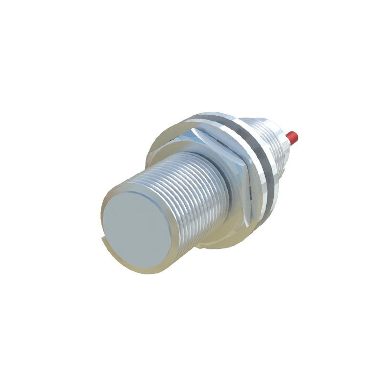
Key technical parameters define the W12's capabilities. The sensing distance, a critical specification, is usually standardized. For a standard W12 sensor detecting mild steel, this nominal sensing range (Sn) is frequently 4mm. It is crucial to note that this value can vary with different target materials; for instance, the effective range for stainless steel or aluminum is often reduced, requiring consultation of reduction factors provided in datasheets. The sensor operates on a DC supply voltage, commonly within a range of 10-30V DC, ensuring compatibility with standard industrial control voltages. Its output is typically a 3-wire configuration (V+, V-, Signal) with a switching current capacity up to 200mA, sufficient to drive relays, PLC inputs, or indicator lamps directly.
Environmental robustness is a non-negotiable feature for industrial sensors. The W12 is generally built to withstand harsh conditions. It commonly boasts an IP67 or higher ingress protection rating, meaning it is dust-tight and can withstand temporary immersion in water. This makes it suitable for washdown areas in food processing or outdoor applications. Furthermore, many W12 models are designed to resist common industrial interferents like cutting fluids, oils, and coolants. Their housing is often constructed from nickel-plated brass or stainless steel, providing excellent mechanical strength and corrosion resistance.
Application areas for the Proximity Sensor W12 are virtually limitless within factory automation. A primary use is position detection. It can verify if a robotic gripper has picked up a metal part, confirm the end-of-travel position of a pneumatic cylinder with a metallic piston rod, or detect the presence of a metal workpiece on a conveyor belt. In packaging machinery, W12 sensors count metal cans or foil lids. In assembly lines, they ensure components are in place before a welding or riveting operation proceeds. Their fast response time and high switching frequency make them ideal for high-speed counting and speed monitoring on rotating shafts equipped with metal gears or encoder discs.
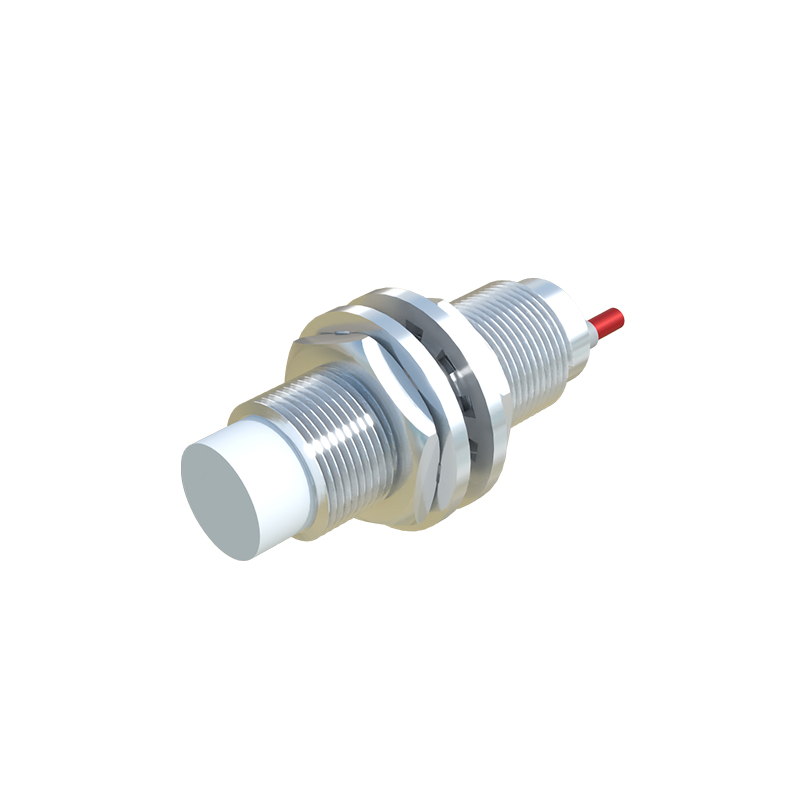
Selecting the correct W12 sensor for a specific task requires careful consideration. First, determine the target material (steel, aluminum, brass, etc.) and the required sensing distance, factoring in any necessary reduction. Next, choose the electrical output type: PNP (sourcing) or NPN (sinking), which must match the input card of the controller (e.g., PLC). The output function, normally open (NO) or normally closed (NC), should be selected based on the safety and logic requirements of the circuit. The operating voltage range must align with the available power supply. Finally, consider special features if needed, such as increased temperature tolerance for foundries, weld-field immunity for areas near resistance welding equipment, or analog current/voltage output variants (often in the same form factor) for distance-proportional measurement instead of simple on/off detection.
Installation and wiring are straightforward but require attention to detail. The sensor should be mounted securely using its integral hex nut. For shielded models, they can be flush-mounted in metal without affecting the sensing range, which is advantageous for mechanical protection. Proper wiring is essential: connect the brown wire (typically) to the positive DC supply, the blue wire to the negative (0V), and the black wire as the switched signal output. Always ensure the load (e.g., PLC input) is connected between the output wire and the positive or negative rail, depending on the PNP/NPN type. Adherence to the manufacturer